Transcription of Seismic Coefficients for Pseudostatic Slope Analysis
1 1 Senior Staff Engineer, Kleinfelder, Inc., Pleasanton, USA. Email: Professor, University of Idaho, Moscow, USA. Email: World Conference on Earthquake EngineeringVancouver, , CanadaAugust 1-6, 2004 Paper No. 369 Seismic Coefficients FOR Pseudostatic Slope ANALYSISC ristiano MELO1 and Sunil SHARMA2 SUMMARYP seudostatic Analysis is one of the simplest approaches used in earthquake engineering to analyze the seismicresponse of soil embankments and slopes. However, the choice of Seismic Coefficients used in the analysiscan be arbitrary and generally lacks rationale. To investigate this, a parametric study was performed on a soilembankment of varied geometric characteristics and soil properties subjected to three different strong groundmotions obtained during the 1994 Northridge earthquake. The dynamic response of the embankment modelwas used to calculate Seismic coefficient time histories for critical failure surfaces generated throughconventional limit equilibrium Analysis .
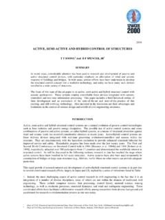
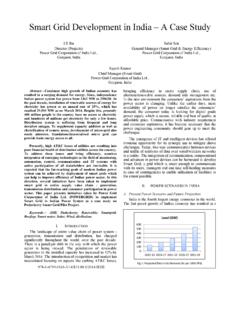
2 FLAC, a two-dimensional explicit finite difference programdeveloped by the Itasca Consulting Group for engineering mechanics computations, was used for the dynamicanalysis. The soil behavior was modeled by the Mohr-Coulomb constitutive relationship. Once the seismiccoefficient time histories were obtained, a procedure was used to compute weighted average seismiccoefficients for each of the time histories. The weighted average Seismic Coefficients obtained in this fashionwere analyzed for possible correlations with the parameters used in the study. The results obtained shouldprovide a more rational approach for selecting Seismic Coefficients for Pseudostatic INTRODUCTIONL imit equilibrium Analysis has traditionally been used to assess the stability of slopes. This procedureconsists of analyzing the cross section of the potential slide mass, called the failure surface (refer to line abin Figure 1), as either a circular or non-circular surface.
3 The area enclosed between the Slope face and thefailure surface, known as the failure mass, is subdivided into a series of slices which are then analyzed forequilibrium by several computational methods. In earthquake prone areas, horizontal and verticalpseudostatic ( Seismic ) Coefficients , kh and kv, respectively, are used to compute the horizontal and verticalforces caused by a potential earthquake, as shown in Figure 1. These forces are in turn added to the overallequilibrium computation for the individual slices composing the failure surface. Studies based on Newmark sdisplacement-type Analysis (Newmark [1]) and field observations indicate that the Pseudostatic method canbe useful in evaluating the performance of embankments constructed of soils that do not lose significantstrength during earthquakes. Such soils include clays, clayey soils, dry or moist cohesionless soils, and densecohesionless soils (Seed [2]).Figure 1 Pseudostatic Analysis of an appropriate Seismic coefficient is the most important, and difficult, aspect of a pseudostaticstability Analysis .
4 In theory, the Seismic coefficient values should depend on some measure of the amplitudeof the inertial force induced in the Slope by the dynamic forces generated during an earthquake. Because soilslopes are not rigid and the peak acceleration generated during an earthquake last for only a very short periodof time, Seismic Coefficients used in practice generally correspond to acceleration values well below thepredicted peak accelerations (Kramer [3]). However, the choice of Coefficients used in the Slope stabilityanalysis is very subjective and lacks a clear rationale. Table 1 below shows horizontal Seismic coefficientvalues that have been recommended for 1 Recommended Horizontal Seismic CoefficientsHorizontal SeismicCoefficient, - the United - severe earthquakesTerzaghi [4] violent, destructive catastrophic - [2], FOS $ Earthquake, FOS > of Engineers [5] Earthquake, FOS > to a of PHAM arcuson [6], FOS > of PHAH ynes-Griffin [7], FOS > = Factor of Safety.
5 PHA = Peak Horizontal Acceleration, in g shown in Table 1, there are no specific rules for selection of an appropriate Seismic coefficient for , the different selection criteria suggest that the Seismic coefficient should be based on the anticipatedlevel of acceleration within the failure mass and should correspond to some fraction of the anticipated peakacceleration (Kramer [3]).Due to the limitations in the selection process of Seismic Coefficients used in design, a parametric study wasperformed on a soil embankment of varied geometric characteristics and soil properties subjected to threedifferent strong ground motions obtained during the 1994 Northridge earthquake. The two-dimensionalexplicit finite difference program FLAC was used to perform the static and dynamic analyses of theembankment. Based on the Seismic response obtained from FLAC, Seismic Coefficients were computed forthe different embankment slopes analyzed. It is hoped that the results of the study will allow practitionersto choose Seismic Coefficients based on the specific geometry and properties of a Slope , as well as thecharacteristics of a specific design NUMERICAL Analysis OF SLOPESThe finite element method has been used extensively to analyze stresses in a variety of man-made and naturalslopes, especially embankment slopes where the desired stresses are often located along a curved failuresurface through the interior of the embankment.
6 The accuracy of a finite element Analysis depends on thetype of element used, fineness of mesh, mesh layout, the geometry of the problem, and the constitutive modelused to simulate the stress-strain behavior of the soils. The different discretization schemes used in finiteelement Analysis of slopes during the last three decades show great variability in the size and shape of theelements used. For an embankment of height H, element heights range from H/4 to H/25, with H/10 beingthe most popular value. The most commonly used element is either a three or four node element, but in thelast decade, eight and nine node elements have become more common. The element aspect ratios(height/width) have usually been close to one, but ranging from 1/3 to 3 (Ashford [8]).Several computer programs that are based on either the finite element or the finite difference method havebeen used to perform Seismic Analysis of soil embankments. Some examples of programs used to performseismic Analysis of soil embankment slopes include QUAD-4, FLUSH, and FLAC.
7 The set of algebraicequations solved by the finite difference method is identical to that solved with the finite element method fora given number of element shape functions. However, in the finite difference method, the set of algebraicequations is solved using dynamic relaxation, an explicit, time-marching procedure in which the full dynamicequations of motion are integrated step by step. Static solutions are computed by including damping termsthat gradually remove kinematic energy from the system (Dawson [9]).Version of FLAC, which stands for Fast Lagrangian Analysis of Continua, was used in the parametricstudy discussed here (Itasca Consulting Group [10]). FLAC is a time domain, two-dimensional explicit finitedifference program used for engineering mechanics computations. This program is primarily intended forgeotechnical engineering applications and simulates the behavior of models/structures composed of soil, rock,or other materials that may undergo plastic flow when their yield limits are reached.
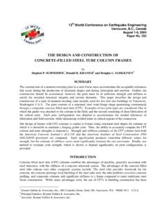
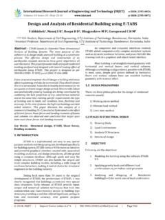
8 Materials are representedby quadrilateral elements, which form a mesh or grid that is shaped as the object to be modeled. Elementsand grid points are numbered in a row-and-column fashion rather than in a sequential manner. The programuses two dimensional arrays (I,J) and (i,j) to define the elements and nodes, respectively, within its discretemesh. An uppercase I and a lowercase i specify the location of an element and a node, respectively,columnwise, from left to right, starting at column one, while an uppercase J and a lowercase j specifythe location of an element and a node, respectively, rowwise, from bottom to top, starting at row one. Thegrid elements within the mesh behave according to a prescribed linear or non- linear stress/strain behavior inresponse to the applied forces or boundary restraints. The material can yield and flow, and the mesh candeform and move with the material that is represented. FLAC has ten built-in material models. For dynamicanalysis, user-specified acceleration, velocity, or stress waves can be input directly to the model either as an(1)Figure 2 Embankment model used in the boundary condition or as an interior excitation to the model.
9 The program contains absorbing andfree-field boundary conditions to simulate the effect of an infinite elastic medium surrounding the Analysis OF SLOPES USING FLACThe model used in the study consisted of a homogeneous earth embankment of varying heights, H, and slopegrades, H:V, overlying a 5-meter thick homogeneous soil foundation layer, as shown in Figure 2. Thefoundation layer was underlain by bedrock. The soil behavior was modeled in FLAC as a linear , perfectlyplastic material with a Mohr-Coulomb yield condition and an associated flow rule. No tension cut-off wasspecified, and the Mohr-Coulomb yield condition was assumed to be valid in the tensile normal stressdomain, which meant that the failure envelope intersected the normal axis at -c/tan . Small-strain mode wasused for the static portion of the analyses ( , the coordinates of the grid points composing the finitedifference mesh were not updated according to the computed nodal displacements).
10 Large-strain mode wasused for the dynamic portion of the study, such that grid coordinates were updated based on nodaldisplacements. No water table was specified for the study and pore water pressures were assumed to be different embankments were first analyzed for static conditions to allow for the computation of staticstresses along their respective critical failure surfaces once static equilibrium was reached. Then, theembankments were subjected to three different earthquake acceleration time histories to permit thecomputation of the dynamic stresses along their respective critical failure surfaces. The difference in stressesfor the dynamic and static conditions was then used to calculate Seismic coefficient time histories. Next, aweighted average was taken of the computed Seismic coefficient time histories, as discussed in Section Embankment ParametersThe four parameters varied throughout the study are shown in Figure 2, and included the embankment sheight, H, the embankment s and its foundation s shear wave velocity, VS1 and VS2, the embankment s slopeface grade, H:V, and the input acceleration time histories.