Transcription of Semiconductor Diodes - Learn About Electronics
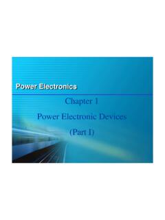
1 semiconductors 1 E. COATES 2016 Semiconductor Diodes Module Diodes Introduction Diodes are one of the simplest, but most useful of all Semiconductor devices. Many types of diode are used for a wide range of applications. Rectifier Diodes are a vital component in power supplies where they are used to convert AC mains (line) voltage to DC. Zener Diodes are used for voltage stabilisation, preventing unwanted variations in DC supplies within a circuit, and to supply accurate reference voltages for many circuits.
2 Diodes can also be used to prevent disastrous damage to battery powered equipment when batteries are connected in the wrong polarity. Signal Diodes also have many uses in processing signals in electronic equipment; they are used to obtain the audio and video signals from transmitted radio frequency signals (demodulation) and can also be used to shape and modify AC signal waveforms (clipping, limiting and DC restoration). Diodes are also built into many digital integrated circuits to protect them from dangerously large voltage spikes. Module 2 What you ll Learn in Module Section Common types of Diodes types of diode , basic operation & characteristics.
3 Section Silicon Rectifiers Rectifier construction & parameters. Section Schottky Diodes Construction, applications, advantages & disadvantages. Section Small Signal Diodes Operation & applications. Section Zener Diodes Operation & characteristics. Section LEDs Operation & testing. Section LASER Diodes LASER operation, construction & Safety considerations. Section Photodiodes Construction operation of PIN & avalanche photodiodes. Section Testing Diodes Circuit Symbols, construction & characteristics Section Diodes quiz Figure Diodes semiconductors Module 2 Diodes semiconductors MODULE 2 PDF 2 E.
4 COATES 2016 LEDs produce light of many colours in a very wide range of equipment from simple indicator lamps to huge and complex video displays. Photo Diodes also produce electrical current from light. Diodes are made from Semiconductor materials, mainly silicon, with various compounds (combinations of more than one element) and metals added depending on the function of the diode . Early types of Semiconductor Diodes were made from Selenium and Germanium, but these diode types have been almost totally replaced by more modern silicon designs.
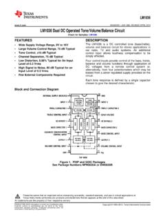
5 Fig. shows a selection of common wire ended Diodes as follows: 1. Three power rectifiers, (a Bridge rectifier for use with mains (line) voltages, and two mains voltage rectifier Diodes ). 2. A point contact diode (with glass encapsulation) and a Schottky diode . 3. A small signal silicon diode . 4. Zener Diodes with glass or black resin encapsulation. 5. A selection of light emitting Diodes . Counter-clockwise from red: Yellow and green indicator LEDs, an infra red photodiode, a 5mm warm white LED and a 10mm high luminosity blue LED. diode Circuit Symbols A diode is a one-way conductor.
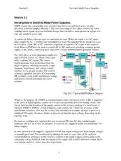
6 It has two terminals, the anode or positive terminal and the cathode or negative terminal. Ideally a diode will pass current when its anode is made more positive than its cathode, but prevent current flow when its anode is more negative than its cathode. In the circuit symbols shown in Fig. , the cathode is shown as a bar and the anode as a triangle. On some circuit diagrams the anode of a diode may also be indicated by the letter a and the cathode by the letter k . Which way does diode current flow? Notice from Fig. that conventional current flows from the positive (anode) terminal to the negative (cathode) terminal although the movement of electrons (electron flow) is in the opposite direction, from cathode to anode.
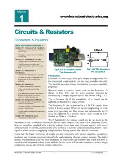
7 Silicon diode Construction Modern silicon Diodes are generally produced using one of various versions of the planar process, also used for manufacturing transistors and integrated circuits. The layered construction used in Silicon Planar methods give a number of advantages such as predictable performance and reliability as well as being advantageous to mass production. A simplified planar silicon diode is illustrated in Fig. Using this process for silicon Diodes produces two differently doped layers of silicon, which form a PN junction . Un-doped or intrinsic silicon has a lattice structure of atoms, each having four valence electrons, but P type silicon and N type silicon are doped by adding a relatively very small amount of material having either an atomic structure with three valence electrons ( Boron or Aluminium) to make P type, or five valence electrons ( Arsenic or Phosphorus)
8 To Fig diode Circuit Symbols Fig Silicon Planar diode semiconductors Module 2 Diodes semiconductors MODULE 2 PDF 3 E. COATES 2016 make N type silicon. These doped versions of silicon are known as extrinsic silicon. The P type silicon now has a shortage of valence electrons in its structure, which can also be considered to be a surplus of holes or positive charge carriers, whereas the N type layer is doped with atoms having five electrons in its valence shell and therefore has a surplus of electrons, which are negative charge carriers.
9 diode PN Junction When P and N type silicon are brought together during manufacture, a junction is created where the P type and N type materials meet, and holes close to the junction in the P type silicon are attracted into negatively charged N type material at the other side of the junction. Also, electrons close to the junction in the N type silicon are attracted into the positively charged P type silicon. Therefore along the junction between the P and N type silicon, a small natural potential is set up between the P and N Semiconductor material with negatively charged electrons now on the P type side of the junction, and positively charged holes on the N side of the junction.
10 This layer of opposite polarity charge carriers builds up until it is just sufficient to prevent the free movement of any further holes or electrons. Because of this natural electrical potential across the junction, a very thin layer has been formed between the P and N layers at the PN junction that is now depleted of charge carriers and so is called the Depletion Layer. When a diode is connected into a circuit therefore, no current can flow between anode and cathode until the anode is made more positive than the cathode by a forward potential or voltage(VF) at least sufficient to overcome the natural reverse potential of the junction.