Transcription of Septum Polarizers and Feeds - W1GHZ.org
1 Septum Polarizers and Feeds Paul Wade, W1 GHZ 2003 The Septum feed1,2 was first described by Zdenek, OK1 DFC, at the 10th International EME Conference 2002 in Prague. On-the-air results were promising, but, like any new antenna, there were questions as to how well it really works. To find out, I ran some computer simulations and published the results3 suggesting that this feed should work well, and also suggesting some variations to allow use over a range of dish f/D. However, I later realized that I was not properly analyzing the circular polarization, so this paper includes revised analysis of the previous Feeds as well as additional results. OK1 DFC Septum feed The Septum feed as described by OK1 DFC is an unflared square horn, or simply a square waveguide, with an internal stepped Septum to generate circular polarization.
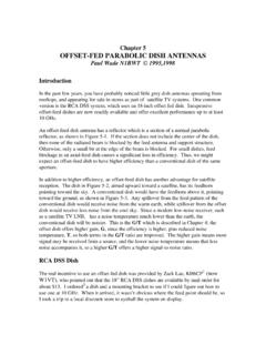
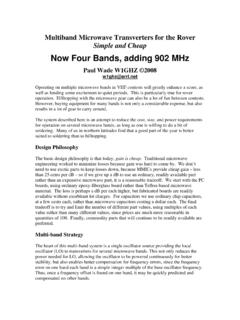
2 Figure 1 is the view looking into the horn, and Figure 2 is a photo of a partially assembled feed with the Septum in place, and Figure 3 is a cartoon of a Septum feed . The horn is excited by inputs on either side of the Septum , with the two sides exciting opposite senses of circular polarization. For EME, this provides separate transmit and receive ports of opposite sense of polarization reflecting off the moon reverses the sense of the polarization. The excitation may come from two rectangular waveguides, each matching the dimensions of one-half of the square horn, or from a perpendicular probe on each side of the Septum acting as an integral transition from coax to the waveguide.
3 The two methods should provide identical results provided that the waveguide section before the Septum is long enough to suppress any spurious modes. The radiating element, at the aperture, is simply a square horn. Rotated 45 degrees, it is identical to a diagonal horn4; if the diagonal horn is excited with circular polarization, then the radiated pattern should be identical. N7 ART has shown5 the diagonal horn to be a good feed , so we might expect the Septum feed to be also. The version described by N7 ART used phased crossed dipoles to generate circular polarization, an arrangement that seems awkward at higher frequencies. The Septum could be a better way to generate circular polarization.
4 Circular Polarization Most antennas radiate linear polarization; most communication antennas use either horizontal or vertical linear polarization. Only a few types, like the helical antenna, have inherent circular polarization. Polarization is defined as the plane in which the electric field, the E-field, varies. For example, a vertically-polarized antenna, like a vertical dipole, has an electric field which at one instant might be positive at the top and negative at the bottom; half a cycle later, it would reverse direction, to be positive at the bottom. In between, a quarter-cycle from the peaks, it would instantaneously pass through zero. To generate circular polarization with linearly-polarized antennas, we must add a second radiator polarized at right angles to the first, and excite it a quarter cycle (90 ) later than the first, so that the electric field of the second radiator reaches a peak as the first passes through zero, and vice-versa.
5 Thus, the positive end of the electric field travels in a circle rather than just reversing along a line. Since the field is also radiating from the antenna at the speed of light as it travels in a circle, we might visualize the positive end as travelling along a corkscrew. Circular polarization is characterized by the direction of travel right-hand (RHCP) or left-hand (LHCP), like the threads on a machine screw. One way to excite the second radiator a quarter-cycle later is to add an extra quarter-wavelength of transmission line; choosing which linear polarization is delayed controls the direction of circular rotation. Another common method for producing the delay is the use of a 90 hybrid a directional coupler with two outputs of equal amplitude but 90 phase difference.
6 In waveguide, a thin dielectric sheet or card will delay energy polarized parallel to the plane of the sheet, but not perpendicularly polarized energy; the length of the sheet may be chosen to provide a quarter-wavelength of delay. A circular waveguide linearly excited at a 45 angle to a card with delay will generate circular polarization. The 45 excitation is mathematically equivalent to two orthogonal components, but only the component parallel to the dielectric is delayed. The dielectric may be a material, like Teflon, or an artificial dielectric, for instance, a row of screws6 in the waveguide, adjusted to provide the desired delay for circular polarization.
7 The Septum is a bit more complicated. A circularly polarized wave entering the aperture may be considered to have two polarization components with a 90 phase difference, one parallel to the Septum and one perpendicular. The parallel component is divided equally by the Septum and passes to the two rectangular input waveguides. The cutoff frequency for the perpendicular component is changed by the Septum , so that the wavelength for the perpendicular component is shorter. Thus, the electrical length of the Septum is longer for the perpendicular component than for the parallel component; if the difference in length is , or 90 , then the horizontal and vertical components arrive in phase at the input.
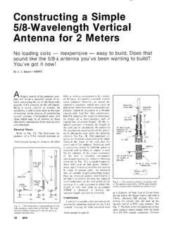
8 The components add together on one side and cancel on the other, depending on the sense of circular polarization, so that the two ports are isolated from each other. In order to achieve the difference in electrical lengths in a reasonable physical distance, the Septum polarizer operates near the cutoff wavelength of the waveguides. Figure 4 shows the simulated E-field distribution in a transparent Septum feed , with the polarization component perpendicular to the Septum visible through the left wall and the parallel component visible through the top wall. The red areas of high field intensity are separated by g along each wall, so we can see that the top and side are g apart at the aperture end, but go through a more complex difference around the steps in the Septum .
9 The cancellation at the input probe on the far side is also clear. The first Septum polarizers7 used a sloping Septum , with a linear taper around 30 , like the cartoon cutaway in Figure 5. This version apparently8 offered limited bandwidth and isolation, so the stepped septum9 was developed to improve isolation and bandwidth. These references state that the field solution around the Septum is very difficult so no analytic procedure is available. However, Chen & Tsandoulas9 show an example with dimensions. OK1 DFC used their dimensions to build a spreadsheet that scales the design for other frequencies. Since the example is for a square horn, and we don t know how to calculate Septum dimensions for other horn sizes, we are limited to this size horn for the Septum section.
10 It should work equally well at any frequency as long as all the dimensions are scaled. When I originally analyzed the Septum Feeds , I saw that the polarization ratio, the ratio of desired to undesired polarizations, was high. Thus, I felt it would be reasonably accurate to calculate efficiency using only the desired circular polarization. Later, I noticed that some of the Septum variations had large rear lobes containing undesired polarizations, even though the polarization ratio in the main lobe was large. As a result, I modified the efficiency calculation to more correctly calculate efficiency as the energy illuminating the dish with the desired polarization divided by the total power in all polarizations, integrated over the reflector as described by Cutler10 and W7 PUA11.