Transcription of Series 3800 MEGA-COUPLING Restrained Coupling
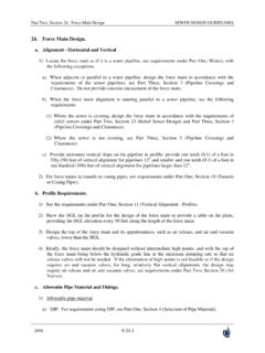
1 Special Notes For Use On HDPE PipeFor use on 4 inch through 12 inch HDPE only. The use of a pipe wall stiffening insert is required for use on HDPE pipe . The stiffeners must be sized to encompass the entire bearing length of the restraint devices. pipe systems must be engineered to prevent movement causing fitting to slide or products for HDPE are designed for underground pressurized fluid service and are pressure rated to match the pipe SDR pressure rating, de-rated as appropriate for service temperature. Maximum test pressure limited to pipe rated Series 3800 Restrained CouplingFeatures and Applications:For use on: Ductile Iron pipe , 4 in.
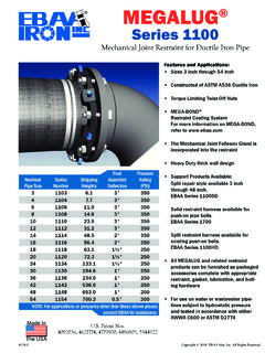
2 - 54 in. c900 or ASTM D2241 PVC pipe , 4 in. - 12 in. c900 -16 PVC pipe , 14 in. - 36 in. Carbon Steel pipe , 4 in. - 12 in. HDPE pipe , 4 in. - 12 2 to 1 Safety FactorMEGA-BOND Restraint Coating SystemFor more information regarding MEGA-BOND, refer to our web site at of: Restraint Rings - ASTM A536 Ductile Iron (DI) Coupling Sleeve - 4 - 12 in., ASTM A536 DI Coupling Sleeve - 14 in. and greater, Carbon Steel Double Ended Threaded Rods w/Nuts - Corrosion Resistant, low alloy, high strength steel per ANSI/AWWA C111 meets or exceeds the applicable requirements of: AWWA C219 ASTM A536 ANSI/AWWA C111 ASTM D2000 Image depicts Series 3806 on 6 inch ductile iron pipe and 6 inch PVC 2018 EBAA Iron, SizeSeriesNumber Shipping WeightDuctile Iron , , , Ratings (PSI)HDPE PipeC900-16 PVC PipeThe Series 3800 are designed to restrain forces based on the maximum working pressure ratings listed in the pressure Ratings experienced due to expansion/contraction of the pipe require special use on water or wastewater pipelines subject to hydrostatic pressure and tested in accordance with either AWWA C600 or ASTM units are pounds and are approximate values.
3 See Page 3 of this brochure regarding specifying proper Series *A2**CSample SpecificationJoint restraint to prevent axial separation shall be incorporated into the design of the sleeve or Coupling used to connect two plain ends of same or dissimilar materials, such as Ductile Iron pipe , steel pipe , PVC pipe ( c900 or ASTM D2241) and or High Density Polyethylene (HDPE) pipe . Internal pipe wall stiffeners must be used when restraining HDPE. The restraint mechanism shall incorporate a plurality of individually actuating gripping surfaces to maximize restraint capability, and have torque limiting twist off nuts to insure proper actuating of the restraint devices.
4 The restraint devices shall be coated using MEGA-BOND . For complete specifications on MEGA-BOND visit Coupling sleeve internal surfaces (wetted parts) shall be lined with a minimum of 15 mils of fusion bonded epoxy conforming to the applicable requirements of ANSI/AWWA C213. The coating shall meet ANSI/NSF-61. Exterior surfaces shall be coated with a minimum of 6 mils of fusion bonded epoxy conforming to the applicable requirements of ANSI/AWWA C116 Ductile Iron components shall meet or exceed the requirements of ASTM A536, and shall be tested in accordance with said standard. Sealing gaskets shall be constructed of SBR and Certified to requirements of ANSI/NSF Restrained joining system shall meet the applicable requirements of AWWA C219, ANSI/AWWA C111 , and ASTM D2000.
5 The Restrained Coupling system shall be Series 3800 manufactured by EBAA Iron, 3800 Submittal Reference Drawing 4 in. - 12 : Dimensions are in inches ( 1%) and are subject to change without SizeSeriesNumber A1 pipe (Maximum)A2 pipe (Minimum)BOverallLengthC Max. Restraint (Casing Clearance)DThrust Bolt(Number-Size)EBarrelLengthMaximum - x - x - x - x - x As installed with Twist-Off nuts off. See following page regarding specifying proper Series B A A I R O NMA D E I N U S A*DIP or c900 OutsideDiameter**ASTM 2241 OutsideDiameter,requires aTransition GasketBEACEBCABECA*Specifying the Proper Series Number4 inch through 12 inchFor Nominal pipe Sizes 4 inch through 12 inch the Series 3800 MEGA- Coupling utilizes a common restraint ring for Ductile Iron pipe (DIP), c900 -16 PVC pipe , ASTM D2241 PVC pipe (IPS), Carbon Steel pipe , and HDPE pipe (with internal pipe wall stiffener for HDPE).
6 The only item that needs to be specified during the order process for 4 inch through 12 inch is what type of gasket is required for joint assembly for the various pipe s: 3800S for Coupling either DIP, c900 -16 PVC and or DIP HDPE pipe 3800T for Coupling either Carbon Steel and or ASTM D2241 PVC 3800ST for Coupling either DIP, c900 -16 PVC or DIP HDPE pipe on one side and either Carbon Steel or ASTM D2241 PVC on the other side14 inch through 54 inchFor Nominal pipe sizes 14 inch and above the Series 3800 MEGA- Coupling utilizes the Series 1100 MEGALUG restraint on DIP and the Series 2000PV MEGALUG restraint on c900 -16 PVC.
7 Since the of both DIP and c900 -16 PVC is the same, the EBAA-SEAL Improved Mechanical Joint Gasket is provided. 3800DI for Coupling DIP 3800PV for Coupling c900 -16 PVC 3800 DIPV for Coupling one side DIP and other c900 -16 PVCE B A A I R O NMA D E I N U S ASeries 3800 Submittal Reference Drawing 14 in. - 54 in.** As installed with Twist-Off nuts : Dimensions are in inches ( 1%) and are subject to change without SizeSeriesNumber*APipe **Max. Restraint (Casing Clearance)Thrust Bolt(Number-Size)EBarrelLengthMaximum - x - x - x - x - x - 1 x - 1 x - 1 x - 1 x - 1 x Iron PIpeC900-16 PVC PipeFor installation on Steel or ASTM D2241 Sized pipe , remove spacers and replace screws.
8 Install per installation on Ductile Iron or c900 PVC sized pipe , use as received and install per Instructions (4 in. through 12 in. only)Ductile Iron or c900 PVC Sized PipeSteel or ASTM D2241 Sized pipe (IPS )Installation Instructions All sizes1. Identify the pipe . The spacers under the actuating screws must be removed for use on ASTM D2241 sized pipe (4 inch through 12 in. only). The spacers must remain in place for use on Ductile Iron or c900 PVC sized and inspect the pipe ends. Beveling of the ends is not used on HDPE pipe , a pipe wall stiffener insert that encompass the entire bearing length of the restraint devices must be installed prior to step two.
9 2. Place the end rings on the pipes with the lip extensions toward the pipe ends. For 4 inch through 12 the restraints will be the Series 2000 HPV, for 14 inch and above Ductile Iron pipe the restraint ring will be the Series 1100 MEGALUG and for c900 PVC 14 inch and above the restraint ring will be the Series 2000PV MEGALUG. Lubricate and install the Standard Mechanical Joint Gasket.(Standard Mechanical Joint Gaskets must be used with Ductile Iron pipe and c900 PVC pipe 4 inch through 12 inch while the EBAA-SEAL Improved Mechanical Joint gasket is used on 14 inch and above. Transition gaskets must be used with Steel or ASTM D2241 pipe ).
10 3. Center the sleeve body over the ends of the pipes while maintaining a 1/2 to 1 gap between the pipe ends. Slide the gaskets and end rings toward the sleeve Install the threaded rods and hand tighten the nuts on each end. Gradually tighten the nuts in an alternating manner until the proper torque value has been reached, while maintaining the same distance between the rings and the ends of the body at all points around the rings. For 4 inch through 24 inch torque to 75 - 90 , for 30 inch and greater torque to 120 - 150 Hand tighten the actuating screws until all wedges are touching the pipes. Continue tightening the screws in an alternating manner until the torque limiting heads twist off.