Transcription of Service Manual - Daikin AC
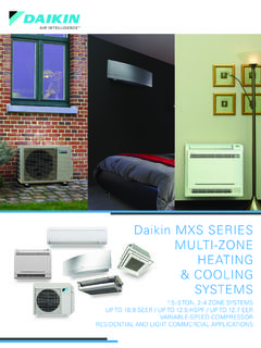
1 Service Manual2/3/4 MXS-N SeriesSiUS121502E[Applied Models]z Inverter Multi : Heat PumpSiUS121502 EiTable of ContentsMulti-Split TypeAir Conditioners2/3/4 MXS-N SerieszHeat PumpIndoor UnitCTXS07 LVJUFDXS09 LVJUFVXS09 NVJUFFQ09 LVJUFTXS09 LVJUFDXS12 LVJUFVXS12 NVJUFFQ12 LVJUFTXS12 LVJUCDXS15 LVJUFVXS18 NVJUFFQ15 LVJUFTXS15 LVJUCDXS18 LVJUFFQ18 LVJUFTXS18 LVJUCDXS24 LVJUFTXS24 LVJUO utdoor Unit2 MXS18 NMVJU3 MXS24 NMVJU4 MXS36 NMVJUSiUS121502 ETable of Contentsii1. Safety Cautions .. Warnings and Cautions Regarding Safety of Workers .. Warnings and Cautions Regarding Safety of Users .. viii2. Used Icons .. xiPart 1 List of Functions .. 11. 2 Part 2 Specifications .. 71. Indoor 82. Outdoor 14 Part 3 Printed Circuit Board Connector Wiring Diagram .. 171. Indoor CTXS07 LVJU, FTXS09/12 LVJU .. FTXS15/18/24 LVJU .. FDXS09/12 LVJU, CDXS15/18/24 LVJU .. FVXS09/12 FFQ09/12/15/18 LVJU .. 262.
2 Wired Remote BRC1E71 .. BRC1E72/73 .. 283. Wireless Remote Controller .. BRC7E830 .. 294. Outdoor 30 Part 4 Function and 331. Function of CTXS, FTXS, CDXS, FDXS, FVXS Series .. Temperature Control .. Frequency Airflow Direction Control (CTXS, FTXS, FVXS Series) .. Fan Speed Control for Indoor Unit .. Program Dry Operation .. Automatic Thermostat NIGHT SET Mode .. ECONO Operation .. INTELLIGENT EYE Operation (CTXS, FTXS Series) .. Inverter POWERFUL Operation .. Clock Setting .. WEEKLY TIMER Operation (CTXS, FTXS, FVXS series) .. Other 532. Function of FFQ Series .. Drain Pump Control .. Thermostat Sensor in Remote Controller .. 56 SiUS121502 EiiiTable of Freeze Prevention Control .. Hot Start Control (In Heating Operation Only).. 593. Control Specification .. Function of Thermistor .. Mode Hierarchy .. Frequency Control.
3 Controls at Mode Changing / Start-up .. Discharge Pipe Temperature Control .. Input Current Control .. Freeze-up Protection Control .. Heating Peak-cut Control .. Outdoor Fan Liquid Compression Protection Defrost Control .. Low Hz High Pressure Limit .. Electronic Expansion Valve Control .. Malfunctions .. 77 Part 5 Remote Controller .. 781. CTXS, FTXS Series .. 792. CDXS, FDXS Series .. 813. FVXS 834. FFQ <BRC1E71> Wired Remote <BRC1E72/73> Wired Remote <BRC7E830> Wireless Remote Controller .. 96 Part 6 Service 971. General Problem Symptoms and Check Items ..992. Troubleshooting with LED .. Indoor Unit .. Outdoor Unit .. 1013. Service Diagnosis .. CTXS, FTXS, CDXS, FDXS, FVXS Series .. FFQ Series .. 1084. Code Indication on Remote Controller .. CTXS, FTXS, CDXS, FDXS, FVXS Series .. FFQ Series .. Outdoor Unit .. 1155. Troubleshooting for CTXS, FTXS, CDXS, FDXS, FVXS Series.
4 Indoor Unit PCB Abnormality .. Freeze-up Protection Control / Heating Peak-cut Control .. Fan Motor or Related Abnormality .. Thermistor or Related Signal Transmission Error (Between Indoor Unit and Outdoor Unit).. Unspecified Voltage (Between Indoor Unit and Outdoor Unit) .. 126 SiUS121502 ETable of Contentsiv6. Troubleshooting for FFQ Series .. Indoor Unit PCB Abnormality .. Drain Level Control System Fan Motor (AC Motor) or Related Abnormality .. Drain System Abnormality .. Thermistor or Related Remote Controller Thermistor Abnormality .. Signal Transmission Error (Between Indoor Unit and Remote Controller) .. Signal Transmission Error (Between MAIN Remote Controller and SUB Remote Controller) .. Field Setting Abnormality .. 1357. Troubleshooting for Outdoor Refrigerant Shortage .. Low-voltage Detection or Over-voltage Detection .. Wiring Error Check Unexecuted.
5 Unspecified Voltage (Between Indoor Unit and Outdoor Unit) / Anti-icing Control in Other Rooms .. Anti-icing Control for Indoor Unit .. Outdoor Unit PCB OL Activation (Compressor Overload) .. Compressor Lock .. DC Fan Lock .. Input Overcurrent Detection .. Four Way Valve Abnormality .. Discharge Pipe Temperature Control .. High Pressure Control in Cooling .. Compressor Sensor System Abnormality .. Position Sensor Abnormality .. CT or Related Abnormality .. Thermistor or Related Abnormality (Outdoor Unit) .. Electrical Box Temperature Rise .. Radiation Fin Temperature Rise .. Output Overcurrent Detection .. 1648. Check .. Thermistor Resistance Check .. Indoor Fan Motor Connector Check .. Hall IC Check .. Power Supply Waveform Electronic Expansion Valve Four Way Valve Performance Check .. Inverter Unit Refrigerant System Check .. Inverter Analyzer Check.
6 Rotation Pulse Check on the Outdoor Unit PCB .. Installation Condition Check .. Discharge Pressure Outdoor Fan System Check .. Main Circuit Short Capacitor Voltage 175 SiUS121502 EvTable of Power Module Check .. 176 Part 7 Trial Operation and Field 1771. Pump Down Operation .. 1782. Wiring Error Check Function .. 1793. Trial Operation .. CTXS, FTXS, CDXS, FDXS, FVXS Series .. FFQ Series .. 1834. Field Settings .. Outdoor Unit .. CTXS, FTXS, CDXS, FDXS, FVXS Series .. FFQ Series .. 1925. Silicon Grease on Power Transistor / Diode Bridge .. 199 Part 8 2001. Piping Diagrams .. Indoor Unit .. Outdoor Unit .. 2042. Wiring Indoor Unit .. Outdoor Unit .. 211 SiUS121502 ESafety Cautionsvi1. Safety CautionsBe sure to read the following safety cautions before conducting repair the repair work is complete, be sure to conduct a test operation to ensure that the equipment operates normally, and explain the cautions for operating the product to the ItemsThe caution items are classified into Warning and Caution.
7 The Warning items are especially important since they can lead to death or serious injury if they are not followed closely. The Caution items can also lead to serious accidents under some conditions if they are not followed. Therefore, be sure to observe all the safety caution items described symbol indicates the item for which caution must be exercised. The pictogram shows the item to which attention must be symbol indicates the prohibited action. The prohibited item or action is shown in the illustration or near the symbol indicates the action that must be taken, or the instruction. The instruction is shown in the illustration or near the Warnings and Cautions Regarding Safety of WorkersWarningDo not store the equipment in a room with successive fire sources ( , naked flame, gas appliance, electric heater).Be sure to disconnect the power cable plug from the plug socket before disassembling the equipment for on the equipment that is connected to the power supply may cause an electrical it is necessary to supply power to the equipment to conduct the repair or inspecting the circuits, do not touch any electrically charged sections of the the refrigerant gas is discharged during the repair work, do not touch the discharged refrigerant refrigerant gas may cause disconnecting the suction or discharge pipe of the compressor at the welded section, evacuate the refrigerant gas completely at a well-ventilated place there is gas remaining inside the compressor, the refrigerant gas or refrigerating machine oil discharges when the pipe is disconnected, and it may cause the refrigerant gas leaks during the repair work, ventilate the area.
8 The refrigerant gas may generate toxic gases when it contacts sure to discharge the capacitor completely before conducting repair step-up capacitor supplies high-voltage electricity to the electrical components of the outdoor charged capacitor may cause an electrical CautionsSiUS121502 EviiDo not start or stop the air conditioner operation by plugging or unplugging the power cable or unplugging the power cable plug to operate the equipment may cause an electrical shock or sure to wear a safety helmet, gloves, and a safety belt when working at a high place (more than 2 m ( ft)).Insufficient safety measures may cause a fall case of R-32 / R-410A refrigerant models, be sure to use pipes, flare nuts and tools for the exclusive use of the R-32 / R-410A use of materials for R-22 refrigerant models may cause a serious accident such as a damage of refrigerant cycle as well as an equipment not mix air or gas other than the specified refrigerant (R-32 / R-410A / R-22)
9 In the refrigerant air enters the refrigerating system, an excessively high pressure results, causing equipment damage and not repair the electrical components with wet on the equipment with wet hands may cause an electrical not clean the air conditioner by splashing the unit with water may cause an electrical sure to provide the earth / grounding when repairing the equipment in a humid or wet place, to avoid electrical sure to turn off the power switch and unplug the power cable when cleaning the internal fan rotates at a high speed, and may cause sure to conduct repair work with appropriate use of inappropriate tools may cause Warnings and Cautions Regarding Safety of UsersBe sure to check that the refrigerating cycle section has cooled down enough before conducting repair on the unit when the refrigerating cycle section is hot may cause the welder in a well-ventilated the welder in an enclosed room may cause oxygen not store the equipment in a room with successive fire sources ( , naked flame, gas appliance, electric heater).
10 Be sure to use parts listed in the Service parts list of the applicable model and appropriate tools to conduct repair work. Never attempt to modify the use of inappropriate parts or tools may cause an electrical shock, excessive heat generation or the power cable and lead wires have scratches or deteriorated, be sure to replace cable and wires may cause an electrical shock, excessive heat generation or not use a joined power cable or extension cable, or share the same power outlet with other electrical appliances, since it may cause an electrical shock, excessive heat generation or sure to use an exclusive power circuit for the equipment, and follow the local technical standards related to the electrical equipment, the internal wiring regulations, and the instruction Manual for installation when conducting electrical power circuit capacity and improper electrical work may cause an electrical shock or sure to use the specified cable for wiring between the indoor and outdoor the connections securely and route the cable properly so that there is no force pulling the cable at the connection connections may cause excessive heat generation or CautionsSiUS121502 EixWhen wiring between the indoor and outdoor units, make sure that the terminal cover does not lift off or dismount because of the the cover is not mounted properly, the terminal connection section may cause an electrical shock, excessive heat generation or not damage or modify the power or modified power cable may cause an electrical shock or heavy items on the power cable.