Transcription of SERVO VALVES - Moog, Inc.
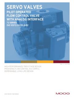
1 SERVO VALVES3-STAGE FLOW CONTROL79 SERIESFOR DEPENDABLE, LONG LIFE OPERATION WHERE POSITION, SPEED, PRESSURE OR FORCE CONTROL SYSTEMS HAVE HIGH DYNAMIC RESPONSE REQUIREMENTSWHAT MOVES YOUR WORLDRev. K, December, 2011 The actual flow is dependent upon electrical command signal and valve pressure drop. The flow for a given valve pressure drop can be calculated using the square root function for sharp edge flow value Q calculated in this way should not exceed an average flow velocity of 100 ft/s in ports P, A, B and T. p Q = QN pN Q [gpm] = calculated flow QN [gpm] = rated flow p [psi] = actual valve pressure drop pN [psi] = rated valve pressure dropIf large flow rates with high valve pressure drops are required, an appropriate higher pilot pressure has to be chosen to overcome the flow forces.
2 An approximate value can be calculated as follows: px 10-2 p Q [gpm] = max. flow p [psi] = valve pressure drop with Q Ak [in2] = spool drive area px [psi] = pilot pressureThe pilot pressure px has to be at least 215 psi above the return pressure of the pilot catalog is for users with technical knowledge. To ensure that all necessary characteristics for function and safety of the system are given, theuser has to check the suitability of the products described here. In case of doubt, please contact Moog SERIES SERVO VALVES The 79 Series flow control SERVO VALVES are throttle VALVES for 3 and preferably 4-way applications.
3 These three stage SERVO VALVES were developed for applications that require high flow rates and high performance. The 79 series covers the range of rated flow from 30 to 200 gpm at 1,000 psi valve drop. These VALVES are offered with 76X Series pilot VALVES , in either Standard, High, or Very High performance configurations. These VALVES are suitable for electrohydraulic position, speed, pressure or force control systems with high dynamic response of operationAn electrical command signal (set point, input signal) is applied to the external control amplifier which drives a current through the pilot valve coils. The pilot valve produces differential pressure in itscontrol ports. This pressuredifference results in a pilotflow which causes mainspool position transducer, which is excited via an oscillator, measures the position of the main spool (actual value, position voltage).
4 The signal then is demodulated and fedback to the control amplifier where it is compared with the command signal. The control amplifier drives the pilot valve until the error between command signal and feedback signal is zero. Thus, the position of the main spool is proportional to the electrical command FEATURESn Electrical feedback on the main spool for low hysteresis and excellent linearityn Optional external pilot supply and return connectionsn High spool control forcesn High dynamics n Rugged, long-life designn High resolution, low hysteresisn Completely set-up at the factoryn Excellent null stability79 SERIESTHREE STAGE SERVO VALVESQAK379 SERIESGENERAL TECHNICAL DATAO perating Pressure Main Stage* Ports P, A and B with X internal up to 5,000 psi with High Pressure Pilot with X external up to 5,000 psi Port T with Y internal up to 3,000 psi Port T with Y external up to 5.
5 000 psi Pilot valve (76X series)* Ports P, A and B up to 5,000 psi Port T up to 3,000 psi Temperature Range Fluid 0 F to 180 F Ambient 0 F to 180 FSeal Material Viton, others on requestOperating Fluid Mineral oil based hydraulic fluid (to DIN 51524), others on request Recommended viscosity 60-450 SUS @ 100 FClass of Cleanliness: The cleanliness of the hydraulic fluid greatly effects the performance (spool positioning, high resolution) and wear (metering edges, pressure gain, leakage) of the valve.* Maximum special order is 5,000 psiRecommended Cleanliness Class For normal operation ISO 4406 < 14/11 For longer life ISO 4406 < 13/10 System Filtration Pilot valve: High pressure filter (without bypass, but with dirt alarm) mounted in the main flow and if possible, directly upstream of the SERVO valve.
6 Main stage: High pressure filter as for the pilot stage. In combination with a fast regulating VD-pump, a bypass filter is Rating recommended For normal operation 10 75 (10 m absolute) For longer life 5 75 (5 m absolute)Installation Options Any position, fixed or 30 g, 3 axesWeight Shipping Plate Delivered with an oil sealed shipping plate. P B T A3 stage SERVO Valve 79-1 XXX Series with a 76X Series pilot valve479-1 XXX SERIESTECHNICAL DATAM odel .. Type 79-1 XXX Mounting Pattern ISO, but X and Y do not correspond to ISO ISO 10372-06-05-0-92 Valve Body Version 4-way 3-stage with spool-bushing assemblyPilot Valve 2-stage, 76X seriesPilot Connection Optional, internal or external X and YMass 24 lbs [ kg] Rated Flow ( 10%) at pN = 1,000 psi [gpm] 30 60 Response Time* for 0 to 100% stroke [ms] 14 14 Threshold* [%] < * [%] < Shift with T = 50 C [%] < Leakage Flow* total, max.
7 [gpm] Spool Stroke [in] .075 Main Spool Drive Area [in2] * measured at 3,000 psi pilot or operating pressure, respectively, and fluid viscosity 32 mm2/s 420-2-4-6-8-12-14-16 Amplitude Ratio (dB)Phase Lag (degrees)100200300020406080100120140160 Frequency (Hz)Optional High Response Frequency Response57102030405070 Supply pressure 3000 psiLoop gain 700 sec-1 10% Spool travel 100% Spool travel420-2-4-6-8-12-14-16 Amplitude Ratio (dB)Phase Lag (degrees)100200300020406080100120140160 Frequency (Hz)Standard Response Frequency Response57102030405070 Supply pressure 3000 psiLoop gain 425 sec-1 100% Spool travel 10% Spool travel 60 gpm30 gpm50010010010005000105 Flow Rate Q (gpm)Rated pressure drop pN= 1,000 psi Valve pressure drop pN [psi]Valve flow for maximum valve opening (100% command signal) as a function of the valve pressure Characteristic Curves measured at 3,000 psi pilot or operating pressure, respectively, and fluid kinematic viscosity of 32 mm2 Flow DiagramFrequency Responsefor VALVES with different rated flows and different pilot valvesSet-up and Angle (degrees)5-50-250+25 Excitation Frequency (kilohertz).
8 (volts/inch)SensitivityvoltSensitivityPh aseNote: Individual units may vary 10%Figure 179-2 XXX SERIESTECHNICAL DATAM odel .. Type 79-2 XXX Mounting Pattern Moog StandardValve Body Version 4-way 3-stage with spool-bushing assemblyPilot Valve 2-stage, 76X seriesPilot Connection Optional, internal or external X and YMass lbs. [ kg] Rated Flow ( 10%) at pN = 1,000 psi [gpm] 100 200 250 Response Time* for 0 to 100% stroke Standard [ms] 15 15 15 High Response [ms] 6 6 6 Threshold* [%] < * [%] < Shift with T = 50 C [%] < Leakage Flow* total, max.
9 [gpm] Spool Stroke [in] Spool Drive Area Standard [in2] High Response [in2] * measured at 3,000 psi pilot or operating pressure, respectively, and fluid viscosity 32 mm2/s420-2-4-6-8-12-14-16 Amplitude Ratio (dB)Phase Lag (degrees)100200300020406080100120140160 Frequency (Hz)Frequency Response200 gpm57102030405070 Supply pressure 3000 psiLoop gain 590 sec-1 10% Spool travel 100% Spool travel420-2-4-6-8-12-14-16 Amplitude Ratio (dB)Phase Lag (degrees)100200300020406080100120140160 Frequency (Hz)Frequency Response100 gpm 57102030405070 Supply pressure 3000 psiLoop gain 700 sec-1 10% Spool travel 100% Spool travel200 gpm130 gpm100 gpm60 gpm5001001001000500010 Flow Rate Q (gpm)Rated pressure drop pN = 1,000 psi Valve pressure drop pN [psi]Valve flow for maximum valve opening (100% command signal)as a function of the valve pressure gpm5 Typical Characteristic Curves measured at 3,000 psi pilot or operating pressure, respectively, and fluid kinematic viscosity of 32 mm2 Flow DiagramFrequency Responsefor VALVES with different rated flows and different pilot Ratio (dB)Phase lag (degrees)100200300020406080100120140160 Frequency (Hz)
10 Frequency Response60 and 100 gpm57102030405070 Supply pressure 3000 psiLoop gain 280 sec-1 10% Spool travel 100% Spool travelHigh Response Valves420-2-4-6-8-12-14-16 Amplitude Ratio (dB)Phase Lag (degrees)100200300020406080100120140160 Frequency (Hz)Frequency Response130 and 200 gpm57102030405070 Supply pressure 3000 psiLoop gain 620 sec-1 10% Spool travel 100% Spool travelStandard ValvesThe mounting Manifold must conform toISO : The X port to ISO Standard must not be machined. The X and Y ports of Moog valve body do not correspond to ISO to which valve is mounted requires a 32 [ ] finish, flat within [ ] SERIESINSTALLATION DRAWINGS WITHPILOT VALVES 76X PER SAE [ ]4X 4 XDASH 20 STR.