Transcription of SERVO VALVES PILOT OPERATED - Moog Inc.
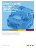
1 HIGH PERFORMANCE, TWO-STAGE DESIGN PROVIDING FLOW CONTROL IN A SIMPLE, RUGGED, DEPENDABLE, LONG-LIFE DESIGNWHAT MOVES YOUR WORLDRev. H, January 2014 SERVO VALVESPILOT OPERATEDFLOW CONTROL VALVEWITH ANALOG INTERFACEG761/761 SERIES, SIZE 04 Moog G761/761 Series Flow Control SERVO ValvesINTRODUCTION2 Whenever the highest levels of motion control performance and design flexibility are required, you ll find Moog expertise at work. Through collaboration, creativity and world-class technological solutions, we help you overcome your toughest engineering obstacles. Enhance your machine s performance. And help take your thinking further than you ever thought Product Overview 3 Features and Benefits 4 Description of Operation 5 TECHNICAL DATA Performance Characteristics 6 Dynamic Characteristics 7 Electrical Data 8 Installation Drawings and Null Adjust Instructions 9 Hole Pattern for Mounting Surface 10 BACKGROUND Null Flow Adjustment 11 Flow Calculation and Null Cut Options 12 Related Products 13 Routine Maintenance Guidelines 14 About Moog 15 ORDERING INFORMATION Accessories and Spare Parts 17 Ordering Code 18 This catalog is for users with technical knowledge.
2 To ensure all necessary characteristics for function and safety of the system, the user has to check the suitability of the products described herein. The products described herein are subject to change without notice. In case of doubt, please contact Moog. Moog is a registered trademark of Moog Inc. and its subsidiaries. All trademarks as indicated herein are the property of Moog Inc. and its subsidiaries. For the full disclaimer refer to the most current information, visit or contact your local Moog H, January, 2014 TABLE OF CONTENTSPRODUCT OVERVIEWThe G761/761 Series flow control servovalves are throttle VALVES for 3 and preferably 4-way applications. They are a high performance, 2-stage design that covers the range of rated flows from 4 to 63 l/min (1 to gpm) at 35 bar (500 psi) valve pressure drop per spool land.
3 The output stage is a closed center, four-way sliding spool . The PILOT stage is a symmetrical double-nozzle and flapper, driven by a double air gap, dry torque motor. Mechanical feedback of spool position is pro vid ed by a cantilever spring. The valve design is simple and rugged for de pendable, long life op era tion. The design is simple and rugged for dependable, long life operation. The output stage is a closed center, 4 way sliding spool . The PILOT stage is comprised of a symmetrical, double nozzle dry torque motor. The 2nd stage spool position is controlled by a carbide tipped feedback wire. The carbide ball on the end of the feedback wire is a mandatory design requirement that ensures high accuracy, reliable operation and long service life. All of our SERVO VALVES are known for high accuracy and reliable operation even in the harshest industrial VALVES are suitable for electrohydraulic position, speed, pressure or force control systems with high dynamic response requirements.
4 Moog G761/761 Series Flow Control SERVO ValvesINTRODUCTIONTIISI ntrinsically safe valve versions are available for use in potentially hazardous environments. Specific models are certified to FM, ATEX, CSA TIIS and IECEx standards. Contact Moog for design 2-stage, with spool and bushing and dry torque motorMounting pattern ISO 10372-004-04-0-92 Maximum operating pressure to ports P, T, A, B 315 bar (4,500 psi) PILOT stage Nozzle FlapperRated flow at pN 35 bar/ spool land 4 l/min 10 l/min 19 l/min 38 l/min 63 l/min(500 psi/ spool land) (1 gpm) ( gpm) (5 gpm) (10 gpm) ( gpm)Step response time for 0 to 100% stroke 5 ms 7 ms 16 ms 3 Rev. H, January, 2014 Features Benefits100% factory tested to ensure critical specification Ensures smooth and easy startup, reduces downtime and performance insures long life in critical industrial applications2-stage design Enables high machine performance, faster cycle times and greater accuracy - all resulting in higher productivityDual Coil torque motor Redundancy for high reliabilityDual Precision Nozzles in Torque Motor Precision flow control and predictabilityDry torque motor design Eliminates potential contamination issues in the air gaps of the torque motor that could cause machine downtimeHardened 440C Bushing and spool Provides for high life, wear resistance when used in the harsh environments.
5 Provides for low sliding friction during useEmergency failsafe positioning Most VALVES are set up to return to a failsafe position when the command signal is interrupted or eliminatedField replaceable PILOT stage filter Enables preventive maintenance in the field, saving precious machine downtime and service costsExternal null bias adjustment Enables technicians to manually adjust the null bias of the valve to adapt to the conditions of the machine (see section on null flow adjustment Page 11). This feature provides a simple adjustment to machine performance without the need to adjust a field configurable 5th port for separate PILOT Provides for the precise control of low pressure supply applicationsCarbide, ball-in-hole feedback mechanism Extends lifetime of SERVO valve when compared to slotted spool and sapphire ball designs FEATURES AND BENEFITSThe G761/761 Series is proven technology that performs reliably in machines where high performance,stability and accuracy are required.
6 Moog s MechanicalFeedback VALVES are designed to provide high reliabilityand long service life. Moog G761/761 Series Flow Control SERVO ValvesINTRODUCTION4 Rev. H, January, 2014 DESCRIPTION OF OPERATIONThe G761/761 Series Flow Control SERVO Valve consists of a polarized electrical torque motor and two stages of hydraulic power amplification. The motor armature extends into the air gaps of the magnetic flux circuit and is supported in this position by a flexure tube member. The flexure tube acts as a seal between the electromagnetic and hydraulic sections of the valve. The 2 motor coils surround the armature, one on each side of the flexure flapper of the first stage hydraulic amplifier is rigidly attached to the midpoint of the armature. The flapper extends through the flexure tube and passes between 2 nozzles, creating two variable orifices between the nozzle tips and the flapper.
7 The pressure controlled by the flapper and nozzle variable orifice is fed to the end areas of the second stage spool . The second stage is a conventional four-way spool design in which output flow from the valve, at a fixed valve pressure drop, is proportional to spool displacement from the null position. A cantilever feedback spring is fixed to the flapper and engages a hole in the center of the spool . Displacement of the spool defects the feedback spring which creates a force on the armature/flapper signal induces a magnetic charge in the armature and causes a deflection of the armature and flapper. This assembly pivots about the flexure tube and increases the size of one nozzle orifice and decreases the size of the differential pressure created by this action causes spool motion.
8 The resulting spool displacement induces a linear force in the feedback wire which opposes the original input signal torque. spool movement continues until the feedback wire force equals the input signal G761/761 Series Flow Control SERVO ValvesINTRODUCTION5 Rev. H, January, 2014 PBTAXS poolFlapperInlet OrificeFlexure TubeCoilConnectorFeedback WireLower PolepieceUpper PolepieceBushingPilot Stage FilterNozzlesMagnet (not shown)ArmatureElectro-hydraulic SERVO Valve Cut-away Rated Flow 4 l/min 10 l/min 19 l/min 38 l/min 63 l/min (1 gpm) ( gpm) (5 gpm) (10 gpm) ( gpm)Tolerance of rated flow 10% of rated flowStep response time for 0 to 100% stroke 5 ms 5 ms 5 ms 7 ms 16 msThreshold of rated signalHysteresis of rated signalNull shift at T = 38 C (100 C) of rated signalG761/761 SERIES SERVO VALVES Moog G761/761 Series Flow Control SERVO ValvesTECHNICAL DATA6 Rev.
9 H, January, 2014 General Technical Data Valve design 2-stage, with spool and busing and dry torque motorPilot stage Nozzle FlapperMounting pattern ISO 10372-04-04-0-92 Installation position Any orientation, fixed or movableWeight kg ( lb)Storage temperature range -40 to +60 C (-40 to +140 F)Ambient temperature range -40 to +135 C (-40 to +275 F)Vibration resistance 30 g, 3 axis, 10 Hz to 2 kHzShock resistance 30 g, 3 axisSeal material Fluorocarbon (FKM) 85 SHORE D Others upon requestHydraulic Data Maximum operating pressure to ports P, T, A, B, X 315 bar (4,500 psi) Rated flow at pN 35 bar/ spool land (500 psi/ spool land) 4/10/19/38/63 l/min (1 gpm)Maximum main stage leakage flow rate (zero lap) l/min ( gpm)Null adjust authority Greater than 10% of rated flowHydraulic fluid Hydraulic oil as per DIN 51524 parts 1 to 3 and ISO 11158.
10 Other fluids on request. Temperature range -40 to +60 C (-40 to +140 F) Recommended viscosity range 10 to 97 mm2/s (cSt) Maximum permissible viscosity range 5 to 1,250 mm2/s (cSt)Recommended cleanliness class as per ISO 4406 For functional safety 17/14/11 For longer life 15/13/10 Recommended filter rating For functional safety 10 75 (10 m absolute) For longer life 5 75 (5 m absolute)Static and Dynamic DataG761/761 SERIES SERVO VALVES Moog G761/761 Series Flow Control SERVO ValvesTECHNICAL DATA7 Rev. H, January, 20141201008060402000102520515 Stroke (% of Rated Signal)Time (ms)Full Amplitude Step Response100% step210 bar (3,000 psi), DTE-24 @ 38 C (100 F)65 l/min ( gpm)Standard Frequency Response63 l/min ( gpm)210 bar (3,000 psi), DTE-24 @ 38 C (100 F)10100100080401201002060-2+2-4-10-80-6 40% 100%Frequency (Hz)Phase Lag (Degrees)Amplitude Ratio (Decibels)010100 40% 100%Frequency (Hz)-2+2-4-10-80-6 Amplitude Ratio (Decibels)100080401201002060 Phase Lag (Degrees)0 40% 100%-2+2-4-10-80-6 Amplitude Ratio (Decibels)10100 Frequency (Hz)100080401201002060 Phase Lag (Degrees)012010080604020006151239 Stroke (% of Rated Signal)Time (ms)12010080604020006151239 Stroke (% of Rated Signal)Time (ms)Full Amplitude Step Response100% step4/10/19 l/min (1 gpm)