Transcription of SEW Bridge Abutment Configuration
1 design Memorandum TO: All design Section Staff FROM: Bijan Khaleghi DATE: October 7, 2011 SUBJECT: SEW Bridge Abutment Configuration Conventional L-shaped abutments and stub abutments on spread footings, piles, or drilled shafts are preferable substructure types for WSDOT bridges. Under conditions where the Abutment requires protection from lateral and vertical loads, a column and crossbeam may be configured with structural earth walls to create an Abutment as shown in Figure 1. This Configuration shall be used only with the approval of the WSDOT Bridge design Engineer. This memorandum is in addition to the requirements of BDM Chapter 7 for Substructure design and Chapter 8 for Wall design . The following guidelines shall be complied with: A Bridge approach slab shall span the void between the back of pavement seat and the SE Wall backfill.
2 The approach slab supports traffic live loads and traffic barrier reactions. The approach slab shall be designed as a beam pinned at the back of pavement seat. The SE Wall backfill shall support the vertical live load surcharge. The approach slab shall not transfer loads to the SE Wall fascia panels. The Configuration shall not be used in scenarios where initial construction cost is the only determining incentive. The design shall include a concrete fascia enclosing the column piers and void. The fascia shall have Bridge inspection access. The access door shall be a minimum 3 -6 square with the sill located 2 -6 from finished grade. Contact the State Bridge and Structures Architect for Configuration and concrete surface treatments. Background: For structural reasons it may be required to construct a complete SEW wall assembly prior to Bridge construction.
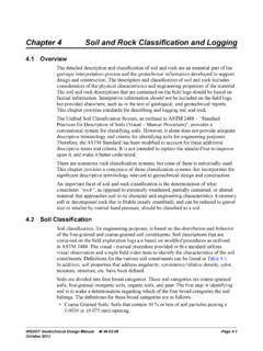
3 In this scenario the Bridge Abutment , constructed using a shaft and column assembly, has had advantages. An enclosing fascia is required to prohibit unwanted access with associated public health, maintenance staff safety, and law enforcement problems. Figure 1. Sectional Elevation showing SE Wall Bridge Abutment Configuration Miscellaneous References The following contracts may be used for guidance: If you have any questions regarding these issues, please contact Paul Kinderman at 705-7159 or Bijan Khaleghi at 360-705-7181. cc: Mark Gaines, Bridge Construction - 47354 F. Posner, Bridge and Structures 47340 Project Name Designer Features Year SR 900 Regional Trail Project Consultant Pedestrian Bridge 2010 I5 City of Marysville Lakewood Consultant Overcrossing with 2010 Access/156th Street Overcrossing I5 Br 5/454 NN Replacement WSDOT Ramp replacement 2011 I5 Puyallup River Bridge WSDOT Major replacement 2011 5/456 Replacement Walls & Buried Structures Chapter 8 SEW Bridge Abutment Configuration Conventional L-shaped abutments and stub abutments on spread
4 Footings, piles, or drilled shafts are preferable substructure types for WSDOT bridges. Under conditions where the Abutment requires protection from lateral and vertical loads, a column and crossbeam may be configured with structural earth walls to create an Abutment as shown in Figure 1. The following guidelines shall be complied with: A. A Bridge approach slab shall span the void between the back of pavement seat and the SE Wall backfill. The approach slab supports traffic live loads and traffic barrier reactions. The approach slab shall be designed as a beam pinned at the back of pavement seat. The SE Wall backfill shall support the vertical live load surcharge. The approach slab shall not transfer loads to the SE Wall fascia panels. B. The Configuration shall not be used in scenarios where initial construction cost is the only determining incentive.
5 C. The design shall include a concrete fascia enclosing the column piers and void. The fascia shall have Bridge inspection access. The access door shall be a minimum 3 -6 square with the sill located 2 -6 from finished grade. Contact the State Bridge and Structures Architect for Configuration and concrete surface treatments. For structural reasons it may be required to construct a complete SEW wall assembly prior to Bridge construction. In this scenario the Bridge Abutment , constructed using a shaft and column assembly, has had advantages. An enclosing fascia is required to prohibit unwanted access with associated public health, maintenance staff safety, and law enforcement problems. The aforementioned are in addition to the requirements of BDM Chapter 7 for Substructure design and Chapter 8 for Wall design . The Abutment Configuration shown in Figure 1 shall be used only with the approval of the WSDOT Bridge design Engineer.
6 The following contracts may be used for guidance: Project Name Designer Features Year SR 900 Regional Trail Project Consultant Pedestrian Bridge 2010 I5 City of Marysville Lakewood Consultant Overcrossing with 2010 Access/156th Street Overcrossing I5 Br 5/454 NN Replacement WSDOT Ramp replacement 2011 I5 Puyallup River Bridge WSDOT Major replacement 2011 5/456 Replacement Figure Sectional Elevation showing SE Wall Bridge Abutment Configuration