Transcription of SHALLOW INTRODUCTION FOUNDATIONS
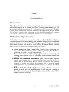
1 1 SHALLOW FOUNDATIONSA ssistant Prof. Berrak TEYMURINTRODUCTIONTo perform satisfactorily: The foundation has to be safe against overall shear failure in the soil that supports it. (bearing capacity) The foundation cannot undergo excessive displacement settlement. Design considerations FOUNDATIONS must be designed both structurally and geotechnically Able to safely carry compression, tension and shear loads, and possible moments Structurally efficient Geotechnically efficient Take tolerance of structure to movement into accountFOUNDATION TYPESSHALLOWSoil layer is suitable for supporting a structure ata relatively SHALLOW depthDEEPDEEPU pper layer of soil is not suitable to carry/supportUpper layer of soil is not suitable to carry/supporta structure. The weight ofa structure. The weight ofthe structure is the structure is transferredtransferredto stable layers at greaterto stable layers at greaterdepths depths ((piles,piles,piers,piers,caissonscaisso ns) ) 2 Typical Footings.
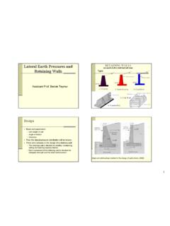
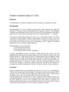
2 A)Single or spread footings, b) stepped footing, c) sloped footing, d) wall footing, e) footing with pedestal (Bowles, 1997)Types; Masonry footings (very light loads) Timber grillage footings (temporary buildings) Steel grillage footings (large shear stresses, heavy loads) Plain concrete footings (light column load) Reinforced concrete footings (high bearing capacity)Single FootingsA strip footing( continuous footing) supports a load bearing wall or group of Footingsupports a number of (Raft) foundationsis a relatively large slab supporting the structure as a whole. Low bearing capacity, but high structural loads Area required for individual/combined footings > 50% of area Heterogeneous soil profile : minimizes differential settlementsBowles, 1997a) Flat plate b) Flat plate thickened under columnsc) Waffle and slabd) Plate with pedestalse) Basement wall as part of mat3i) All loads that may act on FOUNDATIONS should be studied and ) Site investigation should be carried out.
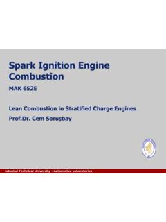
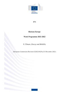
3 Iii) Depth of foundation must be ) FOUNDATIONS must be analyzed with respect to two failure types:1) Settlement failure2) Bearing capacity failureSHALLOW FOUNDATION DESIGNBEARING CAPACITYSafe Bearing Capacityis the value of gross pressure that can be applied without danger of shear Bearing Capacity (qa)is the maximum (net) pressure which may be applied to the soil such that:1. against shear failure of supporting soil is adequate (Fs=2 or 3) total and differential settlements are within permissible Bearing Capacity(qult) is the least (gross) pressure that will cause shear failure in the vicinity of the s Bearing Capacity Theory for SHALLOW FOUNDATIONS According to this theory, a foundation is SHALLOW if the depth, Dfof the foundation is less than or equal to the width of the foundation. Df=3 to 4B considered SHALLOW . Terzaghi suggested that for a continuous or strip foundation, the failure surface in soil at ultimate load may be assumed to be similar to that shown in the figure.
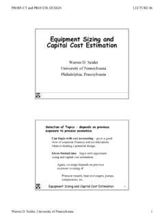
4 The effect of soil above the bottom of the foundation may also be assumed to be replaced by an equivalent surcharge,q= Df. The failure zone under the foundation can be separated into three Capacity (Bowles, 1997)I Active Rankine zoneII Zones of Radial ShearIII Passive Rankine Zone4(Das, 1995)Dense sand or stiff clayLoose sand or soft clay Where ;qu: Ultimate bearing capacityN : Bearing capacity factor due to weight of soil with zerosurchargeNc: Bearing capacity factor due to cohesion of soil, assuming soil to be weightless and surcharge as zeroNq: Bearing capacity factor due to surcharge pressure, q0= D anhorizontal plane at foundation base level, assuming soil below foundation as weightlessFor a square footingwith side BqfcultNDcNBNq ++= a strip footing:qfcultNDcNBNq ++=21 For a circular footingwith diameter D:Note:For a rectangular footing (L*B) use linear interpolation between strip footing (B/L=0) and square footing (B/L= )*For the same soil conditions, for different foundation shapes, qultvalues are ++= = += Terzaghi s Bearing Capacity Factors (Das,1995) 5 Simons and Menzies, 1999 Water Table EffectsBDfOn the bearing capacity of a strip footing on sandqfcultNDcNBNq ++=21 Dwba dry sat(1)(1)(2)(2)(3)(3)(3-3) If depth Dwof water table below base of footing not less than B, then net ultimate bearing capacity qu(net)=qu-Dfqu= cNc+ Df(Nq-1) + BN (2-2) If 0<Dw<B qu= cNc+ Df(Nq-1) + subBN (1-1) Water tabel between foundation level and ground surface ( , 0>Dw>Df)qu= cNc+ (Nq-1) + subBN 0: Initial effective overburden pressure at foundation level.
5 0= dryb+( sat- w)a000 Skempton s Method for Determining NcFor saturated, undrained clays ( u=0); the ultimate bearing capacity of a foundation footing is: Where;Nc: Dependent on shape of footing and B/L , D/BfcuultDNcq +=6(Das, 1995)qcultDNcNNBq ++='21yxeLLeBB2'2' = =Eccentricity tends to decrease the load-bearing capacity of a LoadingDas. 1995 Two way eccentricityQMeQMeBeLeBLQq221121 ; where)661( = == Inclined LoadingIf angle of inclination of resultant load is to the vertical, then bearing capacity factors (N ,Nc& Nq) need to be multiplied by:229011 == = qciiiPILE (DEEP)FOUNDATIONS7 IntroductionPile FOUNDATIONS are used when: The soil near the surface does not have sufficient bearing capacity to support the structural loads. The estimated settlement of the soil exceeds tolerable limits ( Settlement greater than the serviceability limit state) Differential settlement due to soil variability or nonuniform structural loads is excessive.
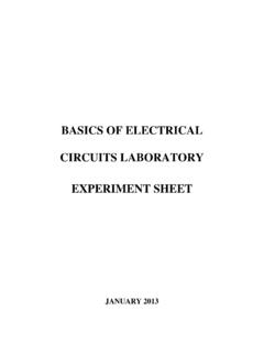
6 The structural loads consist of lateral loads and/or uplift forces Excavations to construct a SHALLOW foundation on a firm soil layer are difficult or Pile Configurations , Bowles, Foundation Types Pile types in terms of material-Timber piles; They are tree trunks that have had their branches and barks carefully trimmed off. The maximum length of most timber piles is 10-20m. Splicing of timber piles should be avoided. -Concrete piles; a) Precast and b) cast-in-situ piles. Pile Foundation Types Pile types in terms of material (cont.)- Precast piles can be prepared by using ordinary reinforcement and they can be square or octagonal in cross section. Reinforcement is provided to enable the pile to resist the bending moment develop during pickup and transportation, the vertical load and the bending moment caused by lateral load.
7 - The piles are cast to desired lengths before being transported to the work sites. Cast-in-place piles are built by making a hole in the ground and then filling with concrete. - Cased and uncased. 8 Pile Foundation Types Pile types in terms of material (cont.)-Steel piles (H-section & pipe piles); Pipe piles can be driven into the ground with their ends open or closed. Steel piles are merged together by welding or riveting (rivets or bolts). Epoxy coatings or concrete encasement of steel piles are done to protect against corrosion. -Composite piles;The upper and lower portions of composite piles are made of different materials. - Steel and concrete- Timber and concreteComparison of Piles Made of Different MaterialsSteel:15-60m Advantages: easy to handle wrtcut-off and extension to the desired length, can stand high driving stresses, can penetrate hard layers such as dense gravel, soft rock, high load-carrying capacity.
8 Disadvantages: Relativelycostly material, high level of noise during pile driving, subject to corrosion, H-piles may be damaged or deflected from the vertical during driving through hard layers or past major of Piles Made of Different MaterialsPrecast Concrete:10-15m (precast) and 10-35m (prestressed)Advantages: can be subjected to hard driving, corrosion resistant, can be easily combined with concrete : difficult to achieve proper cut-off, difficult to of Piles Made of Different MaterialsCased cast-in place concrete:5-15mAdvantages: relatively cheap, possibility of inspection before pouring concrete, easy to : difficult to splice after concreting, thin casing may be damaged during of Piles Made of Different MaterialsUncased cast-in place concrete:5-15mAdvantages: initially economical, can be finished at any : voids may be created if concrete is placed rapidly, difficult to splice after concreting, in soft soils the sides of the hole may cave in, thus squeezing the concrete.
9 Comparison of Piles Made of Different MaterialsWood:10-15mAdvantages: economical, easy to handle, permanently submerged piles are fairly resistant to : decay above water table, can be damaged in hard driving, low load-bearing capacity, low resistance to tensile load when types in terms of load transfer to the soila) Point Bearing Piles: If the presence of bedrock or rocklike material at a site within a reasonable depth, piles can be extended to the rock surface, then the ultimate bearing capacity of the piles depends entirely on the load-bearing capacity of the underlying material. Pile types in terms of load transfer to the soilb) Friction Piles: When no layer of rock or rocklike material is present at a reasonable depth at a site, point bearing piles become very long and uneconomical.
10 Piles are driven through the softer material to specified depths. most of the resistance is derived from skin friction. c) Compaction piles: Piles are driven in granular soils to achieve proper compaction of soil close to ground surface. generally short. floating Pile is a friction pile in which the end bearing resistance is types-Drop hammers,-Steam,-Pneumatic,-Hydraulic,-Di esel hammers,-Vibratory hammers,Pile types in terms of building style-Driven piles,- Bored piles,Determination of Bearing Capacity of Piles1) Static pile capacity:For sands +=+=ssortbqousbuAtanK 'AN 'QQQQ For silts (saturated clays and undrained conditions) +=+=subuusbuA cA9cQQQQPS: is for hard clays and for soft clays as a factor of : ultimate pile capacityQb: load-carrying capacity of pile pointQs: frictional resistanceAb: area of pile tip '0: effective vertical stress at the level of the pile tipcu: undrained cohesion of the soil below the pile tipKs: earth pressure coefficient.