Transcription of Short-Circuit Current Calculations - Cooper Industries
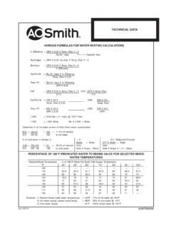
1 237 2014 EatonShort- circuit Current CalculationsBasic Point-to-Point calculation ProcedureStep 1. Determine the transformer full load amps ( ) fromMultiplier = 100*% Ztransformer3 Faultsf = xL xI3 C x n x EL-L1 Line-to-Line (L-L) Faults 2 xL xIL-LSee Note 5 & Table 3f =C x nxEL-L1 Line-to-Neutral (L-N) Faults2 xL xIL-N See Note 5 & Table 3f =C x n xEL-NWhere:L=length (feet) of conductor to the from Table 4 of C values for conductors andTable 5 of C values for busway. n=Number of conductors per phase (adjusts C value forparallel runs)I=Available Short-Circuit Current in amperes at beginningof of primaryM =11 + sym.
2 RMS= Transformer( primaryandf = (%Z) secondaryare100,000 xkVAtransformer3 fault values)1 Transformer( primaryand secondaryaref = primaryxVprimaryx (%Z)1 fault values:100,000 secondaryis L-L)M = 11 + secondary=VprimaryxM primaryVsecondaryeither the nameplate, the following formulas or Table 1:Step 2. Find the transformer multiplier. See Notes 1 and 2* Note %Z from nameplate or Table 1. Transformer impedance (Z) helps to determine what the short circuit Current will be at the transformer impedance is determined as follows: The transformer secondary is shortcircuited.
3 Voltage is increased on the primary until full load Current flows in the secondary. This applied voltage divided by the rated primary voltage (times 100) is theimpedance of the : For a 480 Volt rated primary, if volts causes secondary full load Current toflow through the shorted secondary, the transformer impedance is = .02 = 2%Z.* Note addition, UL 1561 listed transformers 25kVA and larger have a 10%impedance tolerance. short circuit amps can be affected by this tolerance. Therefore, forhigh end worst case, multiply %Z by .9. For low end of worst case, multiply %Z by constructed to ANSI standards have a impedance tolerance (two-winding construction).
4 Step 3. Determine by formula or Table 1 the transformer let-through Short-Circuit Current . See Notes 3 and MultiplierNote voltages may vary 10% for power and for 120 Volt lighting services. Therefore, for highest short circuit conditions, multiply values as calculated instep 3 by or respectively. To find the lower end worst case, multiply results instep 3 by .9 or .942 short circuit contribution, if significant, may be added at all fault locationsthroughout the system. A practical estimate of motor short circuit contribution is to multiply the total motor Current in amps by 4.
5 Values of 4 to 6 are commonly 4. Calculate the "f" 6. Calculate the available short circuit symmetrical RMS Current at the point of fault. Add motor contribution, A. Calculate the "f" factor ( primaryknown)Step B. Calculate "M" (multiplier).Step C. Calculate the Short-Circuit Current at the secondary of thetransformer. (See Note under Step 3 of "Basic Point-to-Point calculation Procedure".) Note 5. The L-N fault Current is higher than the L-L fault Current at the secondary terminals of a single-phase center-tapped transformer. The Short-Circuit Current available(I) for this case in Step 4 should be adjusted at the transformer terminals as follows: AtL-N center tapped transformer terminals, IL-N= x IL-Lat Transformer some distance from the terminals, depending upon wire size, the L-N fault Current is lower than the L-L fault Current .
6 The multiplier is an approximationand will theoretically vary from to These figures are based on change inturns ratio between primary and secondary, infinite source available, zero feet fromterminals of transformer, and x %X and x %R for L-N vs. L-L resistance andreactance values. Begin L-N Calculations at transformer secondary terminals, thenproceed 5. Calculate "M" (multiplier) or take from Table 6A. Motor short circuit contribution, if significant, may beadded at all fault locations throughout the system. Apractical estimate of motor short circuit contribution is tomultiply the total motor Current in amps by 4.
7 Values of 4to 6 are commonly of Short-Circuit Currents When PrimaryAvailable Short-Circuit Current is KnownUse the following procedure to calculate the level of fault Current at the secondaryof a second, downstream transformer in a system when the level of fault Current atthe transformer primary is 2014 EatonShort- circuit Current CalculationsThree-Phase short Circuits M213 System AAvailable UtilityInfinite Assumption1500 KVA Transformer480V, 3 , , X, - 500kcml Cu3 Single Conductors6 Per PhaseMagnetic Conduit2000A SwitchKRP-C 2000SP Fuse400A SwitchLPS-RK-400SP Fuse50 - 500 kcmil Cu3 Single ConductorsMagnetic ConduitMotor Contribution*System BAvailable UtilityInfinite Assumption1000 KVA Transformer480V, 3 , , - 500kcml Cu3 Single Conductors4 Per PhasePVC Conduit1600A SwitchKRP-C 1500SP Fuse400A SwitchLPS-RK-350SP Fuse20 - 2/0 Cu3 Single Conductors2 Per PhasePVC Conduit225 KVA Transformer208V, 3 X1 Step 1.
8 X1000= 2. Multipler 100= Step 3. = 57, motor contribution**= 4 = 7217 AItotal sym RMS= 57,279 + 7217 = 64,496 AFault X1 Step 1. X1000= 2. Multipler =100 = Step 3. = 38,184 AFault X2 Step X25 X57,279= ,185 X6 X480 Step 5. M =1 = + 6. sym RMS= 57,279 = 55, motor contribution**= 4 = 7217 AItotal sym RMS= 55,137 + 7217 = 62,354 AFault X2 Step X30 X38,184= ,706 X4 X480 Step 5. M =1 = + 6. sym RMS= 38,184 = 36,761 AFault X3 Step X50 X55,137= ,185 X1 X480 Step 5. M =1 = + 6. sym RMS= 55,137 = 38, motor contribution**= 4 = 7217 AItotal sym RMS (X3)= 38,067 + 7217 = 45,284 AFault X3 Step X20 X36,761= X 11,424X480 Step 5.
9 M =1 = + 6. sym RMS= 36,761 = 32,937 AFault X4 Step ,937 X480 X( ) = ,000 X225 Step B. M =1 = + C. sym RMS= 480 X32,937 = 32,842A208*See note 4 on page 240.**Assumes 100% motor load. If 50% of this load was from motors. motor 4 X1804 X = 3,608A See note 2 on page 240 = = 1234 One-Line DiagramOne-Line DiagramThis example assumes no motor 2014 EatonShort- circuit Current CalculationsSingle-Phase short CircuitsShort circuit Calculations on a single-phase center tapped transformer systemrequire a slightly different procedure than 3 faults on 3 It is necessary that the proper impedance be used to represent the primary 3 fault Calculations , a single primary conductor impedance is used from thesource to the transformer connection.
10 This is compensated for in the 3 short circuitformula by multiplying the single conductor or single-phase impedance by , for single-phase faults, a primary conductor impedance is considered fromthe source to the transformer and back to the source. This is compensated in thecalculations by multiplying the 3 primary source impedance by The impedance of the center-tapped transformer must be adjusted for the half-winding (generally line-to-neutral) fault diagram at the right illustrates that during line-to-neutral faults, the full primarywinding is involved but, only the half-winding on the secondary is , the actual transformer reactance and resistance of the half-winding condition is different than the actual transformer reactance and resistance of the fullwinding condition.