Transcription of Indianpolis, Indiana 46206-7026 TECHNICAL …
1 WHAT IS NPSH ?Reprinted FromPETROLEUM REFINERBy DAN R. RANKINC hief EngineerPEERLESS PUMP COMPANYTECHNICALINFORMATIONB ulletinNUMBER104 Peerless Pump CompanyIndianpolis, Indiana 46206-7026 Figure 1 Figure Is NPSH ?This term is widely used by engineers but the physical significance is understood by only afew of them. Here is a description of NPSH Dan R. RankinPeerless PumpCompanyAT ANY GIVEN temperature all liquids have a definitepressure at which they boil. Every day we witness the factthat a liquid boils at atmospheric pressure when it reachesasufficiently high temperature.
2 It is important also toremember that a liquid will boil at any temperature if thepressure is reduced sufficiently. It is the problem of theprocess and pump application engineers to make certainthat there is a sufficientpressure on the fluid being fed to thepump so that the liquid does not boil in the suction system ofthe term suction lift is very misleading. No reciprocating gear, turbine vane or centrifugal pump can lift any liquid. It isimperativethat the liquid be forced into the pump for it tooperate properly.
3 The weight of air in the earth s atmosphere is very frequently used to force liquid into the pump suctionand creates the illusion that a pump can lift a liquid. In aclosed process systemwhere atmospheric or other pressurein excess of the liquid vapor pressure is not available theliquid level must always be maintained above the total energy of a liquid is the sum of potential energy(pressure and elevation) and dynamic energy (velocityhead). To maintain a constant total energy any increase inthe velocity of a liquid reduces the pressure a order for a pump to operate, the pressurepushing the liquid into the pump must overcome the staticelevation, the friction and turbulence losses in the suctionline, accelerate the fluid, and maintain sufficient pressure tokeep the fluid in the suction line from are all familiar with the realistic comment made inmany cases of crisis that, Things must get worse before they will get better.
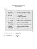
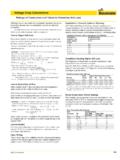
4 This is equally true of the suction conditions of a centrifugal pump. After fluid has finally beenforced through the suction system to the suction flange of apump a pressure drop occurs within the pump before theimpeller can increase the a Pump Requires a Positive Suction HeadA pressure drop occurs between the pump suction flangeand the minimum pressure point within the pump impeller,Figure 5, because of:1) An increase in the velocity between the suction flangeand entrance of the impeller ) Friction and turbulence losses between the suction flangeand entrance to the impeller is impossible to design a centrifugal pump in whichthere isno pressure drop between the suction flange and2 Figure 3 Figure s the Explanation of Cavitation PicturesOn process pumps which are designed with top suction manifolds it ispossible to install plastic plates at the suction of the pump and bymeans of strobotactic lights which flash on and off at the same rate asthe rotation of the pump.
5 Visualize the flow of fluid around the entranceof the impeller vanes. Figure 1 shows a picture of such a pump withtheplastic and plate removed so that the impeller can be seen throughthe suction portion of the pump stages of cavitation are indicated on Figure 2. It is noted thatvapor is beginning to form on the entrance edges of the vanes. Littleno ise or reduction in pump performance is noted in this stage ofcavitation. Impeller vanes may show some pitting after extendedoperation under these conditions especially if there is any tendencytoward corrosion 3 shown the increasedformation of vapor which extends over alarger portion of the entrance of the impeller vanes as a result ofincreasing the suction lift on the pump which decreases the pressureat this area.
6 Normally, some noise would be evident in the pump and areduction in efficiency and head developed by the pump wouldbecome apparent at this 4 indicates severe cavitation at the impeller vanes as thepressure in the pump is further decreased by further increasing thesuction lift. Although the pumpwill still operate under these conditions,it will be noisy, have a reduced head and efficiency. Vibration wouldundoubtedly be noticeable and severe pitting would occur on theimpellers if operated for an extended period of time under to the impeller vanes.
7 All pump systems must have apositive suction pressure sufficiently high to overcome thispressure drop within the pump and to keep the fluid fromboiling at the pumping Water at Sea LevelFigure 6 is a schematic chart showing a general condition ofpump operation where the energy at thesurface of the liquidsource is appreciable greater than the vapor pressure of theliquid being handled. A specific example of this condition ispumping water at room temperature where the liquid source isunder atmospheric pressure at sea level.
8 The energy indicatorto the left shows the total energy at the surface of a watersource at seal level due to atmospheric pressureisapproximately 34 feet. Of this 34 feet, approximately one footmust be maintained at all times to keep the water from leaves essentially 33 feet of energy at the surface of anynormal water source at sea level to force the liquid into pump is shown a the right of the figure with its center lineabove the liquid level. The total useful energy between thecenter line of the pump and the height to which theatmospheric pressure holds the water is indicated by theenergy indicating tube attached to the suction of the the useful pressure which is not available to push theliquid into the pumpbecause of the position of the pump abovethe liquid level.
9 The pressure at the suction flange of the pumpis further reduced by friction and turbulence losses in thesuction line and by the energy which must go into acceleratingthe an absolute pressure gauge were attached to the suctionof the pump exactly as indicated in Figure 6 the liquid wouldstand at the height indicated, designating the useful pressureat this point. As long as the useful pressure above the centerline of the pumpis sufficient to overcome the pressure dropwithin the pump, caused by the increase in velocity and thefriction between the suction flange and the entrance to theimpeller vanes, the pump will continue to operate Liquids With High Vapor PressureFrom Open TanksFigure 7 represents a pumping system for a fluid with highvapor pressure such as acetone with the tank opened to theatmosphere at sea level.
10 The total energy at the surface of theliquid is the same as indicated for water in Figure 6. The liquidwould rise to the level indicated in an absolute pressure gaugestanding in the liquid source. Thus although the total energy atthe surface of the acetone would be identical to that of water,the useful pressure to force the fluid into the pump would beappreciably at a pup installation identical to that in Figure 6, it isnoted that the same friction and velocity pressure losses wouldoccur in the case of acetone assuming it has essentially thesame viscosity as water.