Transcription of VARIABLE FREQUENCY DRIVE - gsengr.com
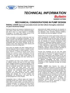
1 VFDRECOMMEN-DATIONSVARIABLE FREQUENCY DRIVEThe synchronous speed of an induction motor isprimarily a function of the number of poles andthe FREQUENCY :A slip between actual and synchronous speed isgenerated by the applied load torque. This slip isusually small, typically 1-3% of synchronous way to achieve a VARIABLE speed motor is to varythe FREQUENCY . Such a device is called a frequencyconverter. FREQUENCY converters, also called vari-able speed drives, are usually installed to allow fora better process control and to save energy. Theusage of VARIABLE FREQUENCY DRIVE (VFD) control inpump applications is becoming increasingly com-mon. The cost of a VFD has decreased over theyears while the performance has improved. Amodern VFD is a compact, well-developed unitwhich is relatively easy to install. Unlike an old VFD, the modern version doesnot require as much power margin (de-rating)and so does not affect the induction motor to thesame extent, this is due to the fact that VFDswitching FREQUENCY is higher today.
2 The highswitching FREQUENCY however, induces transientswhich can lead to other problems such as nuisancetripping of control equipment. This effect can beminimized by using shielded cables and appropria-te filters. Despite the non-ideal VFD problemswith clogging of the pump and sedimentation inpipe systems (due to low velocities) are more like-ly to occur when the speed of the pump is redu-ced. Pumping with VARIABLE FREQUENCY drives can beseparated into two cases. A VARIABLE continuous flow is required by theprocess. The normal way to control the flow isby throttling. The use of VFD control will, inall cases, lead to an energy reduction. VFD vs. on/off regulation. VARIABLE speed driveis used to reduce losses whilst pumping. Theeffect of a VFD depends upon the with a high percentage of friction lossesrelative to the static head are suitable for VFDoperation.
3 More pure lift systems, on the otherhand, are not generally suitable for variableoperation. The FREQUENCY normally decreaseswhen the speed is reduced and there is a riskthat the pump will operate outside allowed ope-rational range. A thorough system analysis hasto be performed in order to determine if variab-le speed control can be economically pumping is a typical applicationwhere VFD and on/off control have to be more information, see Flygt brochure Economical aspects of VARIABLE FREQUENCY drivesin pumping stations .frequencyn = 120 [rpm]# of polesVARIABLE FREQUENCY DRIVE BASIC PRINCIPLE OF A VFDIn theory the basic idea is simple, the process oftransforming the line FREQUENCY to a VARIABLE fre-quency is basically made in two Rectify the sine voltage to a DC-voltage. 2. Artificially recreate an AC-voltage with desiredfrequency.
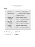
4 This is done by chopping the DC-volt-age into small pulses approximating an ideal VFD consists basically of three blocks: the recti-fier, the DC-link and the inverter . Fig 1. Schematic functions of a VFDRECTI-FIERDC-LINKINVER-TERM3 There are three different types of VFDs: VSI - Voltage Source inverter , PWM. CSI - Current Source inverter . Flux vector CSI has a rough and simple design and is con-sidered to be very reliable, but the output signalmeans a lot of noise. Furthermore the CSI induceshigh-voltage transients in the motor. The flux vec-tor control is a more sophisticated type of VFDwhich is used in applications where the speedshould be controlled very precisely, papermills. This type is expensive and pump applica-tions cannot take advantage of its benefits. Themost common type of VFD, and the one recom-mended by Flygt, is the PWM Pulse WidthModulation.
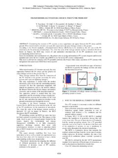
5 Fig 2. Schematic signal from a PWM-type VFDThe PWM-type VFD normally uses a constant voltage which is pulsed with integrated bi-polarpower transistors (IGBT). The sine wave is gene-rated by varying the width of the pulses. The fre-quency which the transistors are turned on and offby, is called switching FREQUENCY . The higher theswitching FREQUENCY , the better the reproductionof the ideal sine wave. The affinity laws state that the flow is proportio-nal to impeller speed at a specific point on thepump curve. Head and NPSH are proportional tothe square of the speed, while the power is a cubi-cal function of the speed. The hydraulic (pump)efficiency remains constant when the speed laws:Ex. A centrifugal pump with nominal frequency50 Hz is running at reduced speed, 35 Hz. Thebest hydraulic (pump) efficiency point for thenominal curve is 74 % at a flow of 93 l/s and ahead of m.
6 Power in best efficiency point(BEP) is kW. New BEP is calculated: Flow decreases proportionally to the FREQUENCY : Head is reduced to Power drops to Hydraulic (pump) efficiency remains the same,74 %.All points on the pump curve will move alongsecond degree curves with constant efficiencytowards the origin of the co-ordinates when thefrequency is 3. FREQUENCY -regulated pump are three different types of VFDs: VSI - Voltage Source inverter , PWM. CSI - Current Source inverter . Flux vector CSI has a rough and simple design and is con-sidered to be very reliable, but the output signalmeans a lot of noise. Furthermore the CSI induceshigh-voltage transients in the motor. The flux vec-tor control is a more sophisticated type of VFDwhich is used in applications where the speedshould be controlled very precisely, papermills.
7 This type is expensive and pump applica-tions cannot take advantage of its benefits. Themost common type of VFD, and the one recom-mended by Flygt, is the PWM Pulse WidthModulation. Fig 2. Schematic signal from a PWM-type VFDThe PWM-type VFD normally uses a constant voltage which is pulsed with integrated bi-polarpower transistors (IGBT). The sine wave is gene-rated by varying the width of the pulses. The fre-quency which the transistors are turned on and offby, is called switching FREQUENCY . The higher theswitching FREQUENCY , the better the reproductionof the ideal sine wave. The affinity laws state that the flow is proportio-nal to impeller speed at a specific point on thepump curve. Head and NPSH are proportional tothe square of the speed, while the power is a cubi-cal function of the speed. The hydraulic (pump)efficiency remains constant when the speed laws:Ex.
8 A centrifugal pump with nominal frequency50 Hz is running at reduced speed, 35 Hz. Thebest hydraulic (pump) efficiency point for thenominal curve is 74 % at a flow of 93 l/s and ahead of m. Power in best efficiency point(BEP) is kW. New BEP is calculated: Flow decreases proportionally to the FREQUENCY : Head is reduced to Power drops to Hydraulic (pump) efficiency remains the same,74 %.All points on the pump curve will move alongsecond degree curves with constant efficiencytowards the origin of the co-ordinates when thefrequency is 3. FREQUENCY -regulated pump actual duty point is always the intersectionbetween the pump curve and the system hydraulic (pump) efficiency in systems with astatic head will change when the FREQUENCY isreduced. The system curve for a system with a sta-tic head does not coincide with the constant effici-ency curves.
9 The duty point will move along thepump curve, towards the left side of the pumpand efficiency curves, (see fig 4 and fig 5).The system curve for a pure loss system willcoincide with a constant efficiency curve, the hyd-raulic (pump) efficiency will remain constantwhen the FREQUENCY is 4. System duty-point movement for a lift system and a pure loss 5. System duty-point movement for a combined system anda pure loss system shown in an efficiency and power The same pump in the previous example isinstalled in a lift system with a static head of 6 duty point for full speed is the same as BEP,93 l/s at m (eff. 74 %) What happens to theduty point when the pump FREQUENCY is regulateddown to 35 Hz? Flow decreases to 26 l/s, (see fig 4). Head is reduced to m, (see fig 4). Shaft power drops to kW (see fig 5).
10 Hydraulic (pump) efficiency is not constant,dropping to 50 % (see fig 5).It is worth noting that the pump stops deliveringflow at 32 Hz in this application. It is recommended, when selecting a pump forVFD duty, that it has its full speed duty point onthe right hand side of the BEP. This is due to thefact that the duty point moves towards the lefthand side of the efficiency curve when the speed isreduced. Thus, hydraulic (pump) efficiency initi-ally will increase when the FREQUENCY is reduced,and the rapid efficiency drop on the curve will notoccur until the speed is reduced of Flygt s pump curves are partially limit-ed due to power or hydraulic limitations causingvibrations induced by re-circulation in the impel-ler. This will not disappear when the speed isreduced, and minimum allowed flow will be pro-portional to the FREQUENCY .