Transcription of Introduction to Logic - TI.com
1 ApplicationReportSLVA700 April2015 Introductionto LogicRyanLandABSTRACTL ogiccircuitsare the buildingblocksof the electronicsuse 1s and 0s (bits) the physicalworld,the 1s and 0s are representedby voltageson a wire,on microscopictraceswithinan integratedcircuit,or on a copperprintedcircuitboard(PCB) storedataby usingcombinationaland manydifferenttypesof logiccircuitsthat will be describedin this report,includinglogicgates,registers,fli p-flops, 1s and0s as voltageson theirinputs,andtheyperformspecificoperat ionson thosesignalsto producean the propersequence,thesedevicescanmanipulate the signalsin sucha way that can resultin anythingfroma simpleaddingcircuitto a makesmicrocontrollerunits,whichcontainmi llionsof smalllogiccircuitsusedto ,TI alsomakesthe individualbuildingblocksas integratedcircuits(ICs)thatengineerscan use to buildsmaller-scaledigitallogicinto also be usedfor voltagetranslationor 1 and 0 in the RealWorld?
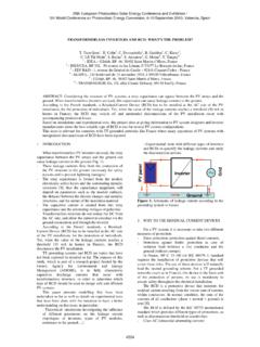
2 Of Figures1 CombinationalLogicGatesand of Tables1 CombinationalLogicGatesCombinationallogi cgates,or simply"logicgates",are the simplesttype of is either1 (high)or 0 (low)dependingin the statesof one or moreof otherwords,they performthe basicfunctionsof the buildingblocksfor describeseachtype of April2015 Introductionto LogicSubmitDocumentationFeedbackCopyrigh t 2015,TexasInstrumentsIncorporatedAYABYAB YABYABYABYABYB ufferInverterOR GateAND GateY = AAYAYY = AABABABABABABY = A + BY = W NOR GateY = A + BNAND GateY = W XOR GateY = A + BXNOR GateY = A + B010101001101010011010100110101001101010 01101010011AY0101100111000110001110 Output matches the is the opposite of the is high if at least one input is is high only if all inputs are is high only if none of the inputs are is high unless all inputs are is high only if an odd number of inputs are is high only if an even number of inputs are name and symbolFunction descriptionTruth CombinationalLogicGatesand theirFunctions1.
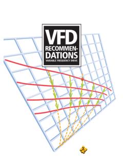
3 Gatenameand symbol:The nameand standardsymbolassociatedwith the gate,includinga standardequationusedto describethe functionit Functiondescription:A verbaldescriptionof whatthe Truthtable:A tabledescribingwhathappensto the outputat everypossiblecombinationof the general,inputsare designated"A, B, C, .." whilethe outputis designatedwith "Y". In truthtables,sometimesthereis an "X" insteadof 0 or 1 listedas an "X" refersto "Don'tCare",andmeansthat particularinputhas no effecton the OR, AND,NOR,NAND,XOR,and XNOR gatesare not limitedto 2 example,a 3-inputANDgate,like the SN74 LVC1G11, requiresthat inputsA, B, and C are all high beforeoutputY will LogicSLVA700 April2015 SubmitDocumentationFeedbackCopyright 2015,TexasInstrumentsIncorporatedCLKDQQQ Q0110Q0 DQCLKQDCLK'0101 XXQ0Q0Q0'SymbolTruth TableFunctional Block DiagramThe D-type flip-flop passes the value of D to the Q output, and the inverse of D to the Q0 output, when a clock edge occurs.
4 Most devices function on the positive clock example,the SN74 LVC2G08contains2separateANDgates,and the SN74 LVC32244contains32 designedfor movingand storageof 1s and 0s. Often,but not always,thesedeviceswill havewhatis knownas a "Clock" ,the clockinputis a square-shapedwaveformthat runsat a constantfrequencyand controlswhenthe deviceperformsa ,a devicemay be designedto outputa specificvalueor movea bit of informationwhenthe risingedgeof the sequentiallogiccircuitsthat can storeone or morebits. Whiletheirdatainputscan changeconstantly,theiroutputswill changeonly whena "clockedge" clockedgeis definedas a changein stateof the "Clock"inputpin on the ,any devicefunctionwill be triggeredby the positive(0 to 1) severaltypesof flip-flops,but the D-typeand JK-typeare the mostcommonin TI's D-typeflip-floptakesthe D inputand pushesits valueto the Q outputon the next alsopushesthe inverseof D to the Q be usedfor temporarydatastorage;forexample,8 D-typeflip-flopsconnectedto the sameclockline will be able to storeone byte of SN74 AUC1G79is an exampleof a TI D-TypeFlip-Flop3 SLVA700 April2015 Introductionto LogicSubmitDocumentationFeedbackCopyrigh t 2015,TexasInstrumentsIncorporatedCLKJQQQ Q101 JQCLKQKCLK901010Q0Q09 SymbolTruth TableFunctional Block DiagramThe Q output of the J-K flip-flop output takes the value of Jif J and K are different.
5 If J and K are both 0, the outputstays the same. If J and K are both 1, the output Flip-FlopThe J-K flip-flopfunctionis slightlymorecomplicatedthanthe ,it can beconvertedto a D flip-flopby placingan inverterin frontof the K inputand tyingthe inputof that invertertothe J SN74 LVC112 Ais an exampleof a TI dual J-K flip-flopthat is triggeredon the negativeedgeof the J-K chainsof flip-flops(usuallyD-type)that propagatedatathroughthe example,for an 8-bitshift register,if the datainputis a 1 and the clockis pulsed8times,thena 1 will be storedin all the inputis 1 for 4 clockpulses,then0 for another4 clockpulses,thenthe final 4 bits of the shift registerwill be 1s and the first 4 bits of the shift registerwill be be usedin manydifferentapplications,includingdrivi nga stringof flashingLEDsorscanninga keyboardfor key SN74LV164 Ais an exampleof a TI shift devicesthat countin binary,startingwith 0, 1, 10, 11, 100,and so on.
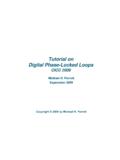
6 Eachtime a clockedgeoccurs,the valuestoredinsideincrementsby 1. Thereare also countersthat startat the maximumvalueand whena counthas generallyusedto dividethe frequencyof a SN74HC393is anexampleof a dual LogicSLVA700 April2015 SubmitDocumentationFeedbackCopyright 2015,TexasInstrumentsIncorporatedVCCVCCV CCVCCVCCVCCVOHVIHVTVILVOLGND5 V0 VVIHVILGNDVOHVIHVTVILVILVOLGND5 V2 V0 V2 V0 V0 V0 VVIHVILGND5V CMOS5V 1 and 0 in the RealWorld?3 Whatare 1 and 0 in the RealWorld?So far in this document,we havediscussedinputsand outputsof logiccircuitsas being"high"(1) or "low"(0). But whatdoesthis meanexactly?In reality,differentfamiliesof discretelogicICs treat"high"and "low" example,somedeviceswill V at the inputas a "high",whileon otherdevices, V is not enoughto reachtheswitchingthresholdand is still considereda "low".The applicationreportUnderstandingand InterpretingStandard-LogicDataSheetshas lots of usefulinformationon everyspecificationin logicdatasheets,but we will discussthe relevantspecificationsforinputand mostcommoninput/outputlevelstandardsare CMOSand TTL,whichcan havedifferentvoltagelevelsand are describedby the levelsin CommonSwitchingInputand OutputLevels VCC: The supplyvoltageof the device VOH: The minimumallowed"high"outputvoltagefor a deviceusingthat example,a 5-V CMOS deviceonly has a validoutput"high"if that outputis at VIH: The minimumallowedinputvoltagefor an inputto be considered"high" VT: The actualpointwherethe switchingoccursfromlow to is typicallynot specifiedin reality,thereis somevariancehere,and thereforeTI specifiesVIHand VILas maximumand minimummarginsfor this switchingthresholdto occur.
7 VIL: The maximumallowedinputvoltagefor an inputto be considered"low" VOL:The maximumallowed"low"outputvoltagefor a deviceusingthat example,a 5-V CMOS deviceonly has a validoutput"low"if the outputis V or ,whendesigninga system,it is criticalthat the designershouldchoosepartswhoseoutputsare compatiblewith the receiver' example,5-V CMOS outputsare compatiblewith 5-V TTL inputsbecausethe VILfor 5-V CMOSis , whichis greaterthanthe 2-V VIHrequiredfor a 5-V TTL inputtobe considered"high".In addition,the 5-V CMOSis less thanthe the 5-V TTL ,a 5-V TTL outputshouldnot go into a 5-V CMOS inputbecausethe 5-V TTLVOLis allowedto be as low as V, whichis not high enoughto guaranteea "high"on the CMOS device;the VIHfor 5-V CMOSis 5 V = ,VOH, and VOLM ostlogiccircuitscan be thoughtof as havingthe sametypesof , for anylogiccircuit,the outputsectionof the device(regardingits performancewith voltage,current,and speed)behavessimilarlyto a bufferin the April2015 Introductionto LogicSubmitDocumentationFeedbackCopyrigh t 2015,TexasInstrumentsIncorporatedVCC IOL IN+ VOLVOLIOL VOL = 0 VRAIL VCC IOH LoadIN+ VOHVOHIOH VOH = VCC datasheetsusuallyspecifyVOHand VOLat differentvaluesof VCCand logiccircuitoutputsa "high",currentis flowingout (IOH) of the deviceinto a be a resistor,LED,otherlogiccircuit,or any othertype of ,the morecurrentthat flowsout of the device,the lowerits outputvoltagewill be.
8 This is due to voltagedropswithintheoutputstageof the datasheetsrecommenda safe operatingcurrentthat doesnot droptheVOHbelowthe standardthat the devicefalls under(5-V TTL, ,and so forth).At extremelysmalloutputcurrentvalues,mostlo giccircuitswill outputa voltageequalto or very closeto VCC. TypicalVOH/IOHR elationshipfor LogicCircuitsSimilarly,whenthe deviceoutputsa "low",currentflowsinto the this case,morecurrentflowinginto the devicecan increasethe VOL, whichshouldideallybe 0 V at low TypicalVOL/IOLR elationshipfor LogicCircuitsMostlogiccircuitshave"push- pull"outputs,meaningthat they can providecurrentand sink "open-collector"or "open-drain"outputs,whichmeansthat they can only sink currentand rely on an externalpullupresistorto providethe "high" an "open-collector"or "open-drain"device,thereare no VOHor may noticedifferentnomenclaturein TI part example,TI producesmanydifferenttypesof single-bitbuffers,includingthe SN74 AUC1G34and SN74 LVC1G34.
9 We classifythesedevicesasbeingfromtwo different"families".Whilethey performthe samefunction,theirspecificationsmay example,the AUCdeviceis characterizedto operateat , but the LVCdeviceis ,the LVCdeviceis characterizedto provideup to 24 mA of outputcurrentwhileretainingitsvalidCMOS outputlevels,whilethe AUCdevicecannotprovideas pick for list of familiesand a shortdescriptionof eachcan be foundin Understandingand LogicSLVA700 April2015 SubmitDocumentationFeedbackCopyright 2015, documentis intendedto give a briefoverviewof TI logicand introducethe readerto specificdevicesand has a widevarietyof applicationreportstargetedat differentapplicationsandissuesengineersm ay followingis a brieflist of full list of logicdocumentsis foundhere. Understandingand InterpretingStandard-LogicDataSheetsis the mostcomprehensiveoverviewofdatasheetpara metersand specificationsfor TI logiccircuits. Voltage-LevelTranslationwith the LSF Familyexplainshow to use TI's LSF0x0xfamilyof devicestotranslatebetweendifferentvoltag elevelsin applicationswheredifferentlogicsignaling standardsareused.
10 Power-UpBehaviorof ClockedDevicesdescribesdangersof assumingcertainoutputstateswhenusingflip -flopsand registers- and whatto do aboutit. Use of the CMOSU nbufferedInverterin OscillatorCircuitsdescribesa low-costway to generateaclocksignal. Power-up3-StateCircuitsin TI StandardLogicDevicesdescribeslevelsof isolationin TI is especiallyusefulin systemswherenot all devicesare poweredon at the sametime. Implicationsof Slowor FloatingCMOSI nputsdescribesthe unwantedeffectsof leavinga logicinputfloating(unconnected)and elaborateson the "InputTransitionRiseor Fall Rate"specificationrequiredof manydevices. Implicationsof Slowor FloatingCMOSI nputsdescribesthe equationsusedto calculatethe typicalpowerconsumptionof a logiccircuitin yourdesign. DesignConsiderationsfor LogicProductscontainsa collectionof applicationreportstargetedat TI'slegacylogic,includingproperPCBlayout ,characterizationinformation,and application-specificdesigncircuits.