Transcription of Simple and Powerful Discreet LDO Voltage Regulator
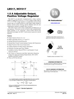
1 Simple and Powerful Discreet LDO Voltage Regulator Do you need a Simple LDO Voltage Regulator , but an IC version that meets your needs is not available? Make your own using this circuit. The circuit in the drawing is the actual circuit that I built and used successfully to power a shortwave radio which I have since sold (with the power supply). It has rock-solid regulation and its current capacity is limited only by the size of the MOSFET you use. Because the MOSFET requires no base current, the zener current is held constant, keeping it from being affected by input or output conditions.
2 Because of the extremely high gain of the Q2/Q3 circuit and the slight phase shift caused by R2 and the gate capacitance of Q1, the circuit is prone to slight instability if not heavily bypassed at the output. You can probably delete C1 as it s just there to protect Q1 from static zaps or Voltage spikes, but you can t delete C2 and you can t delete C3 if the load doesn t already have an input capacitor of similar value. Properly bypassed, the circuit is rock solid. The circuit has ZERO saturation Voltage . That means that the input Voltage can go all the way down to the output Voltage before the output Voltage starts to drop.
3 R3 is there to adjust the output Voltage downward from the volts that the circuit would normally produce to the desired volts. You can use other zeners to change the output Voltage . It is not advisable to use R3 to adjust the output Voltage downward by more than about volts. You can replace D1 with an LM431 and two resistors and get any output Voltage that you want. Do not delete R3 in that case as some oscillation was noted under load with an LM431 and no R3. This is probably because some negative feedback is needed due to the high gain of the LM431.
4 With a zener in place of the LM431, the circuit continued to be stable with R3 removed. With an LM431, I would adjust R3 to drop the output Voltage by about volts to keep the circuit stable. Using a bigger MOSFET (2SJ412) produced a stable output using the LM431, and without R3. Note that the bigger the MOSFET, the slower the response to rapidly changing loads, due to the higher gate capacitance. If this is an issue, use a bigger electrolytic capacitor on the output to smooth out the load. You can also lower the value of R2. With an LM431, you can also substantially reduce quiescent current by replacing R5 with a 470 ohm resistor.
5 With R5 changed to 470 ohms and D1 replaced with an LM431 and two 10K resistors, I got a stable output of volts and of quiescent current. That s good enough for battery operation. Even with this small quiescent current, you can pull loads of current through the Regulator (with a heat sink, of course) and still maintain a precise output Voltage . Replacing Q1 with a PNP transistor (delete R2) produces a much more stable circuit but the output begins to drop when the input Voltage gets within volts of the output Voltage . In that test, Q1 was 2N2905, R5 was 100 ohms and an LM431 was used.
6 Because of no phase shift in Q1, C3 was not needed for stability. R3 is optional in this case if using a zener as D1. Because of the base current of Q1, the performance of this circuit with a zener for D1 will not be as precise as it would be with a MOSFET for Q1. The LM431 would be the best choice here as it is not affected significantly by the current through it and can be adjusted to any Voltage . R5 sets the maximum base current through Q1 plus the minimum current through D1 which is 1ma according to the LM431 datasheet. The temperature coefficient of the circuit will be that of the zener used minus 2mV/degC.
7