Transcription of SIP Call Flows - Cisco
1 A P P E N D I X B. SIP call Flows This appendix includes the following sections: call Flow Scenarios for Successful Calls, page B-2. call Flow Scenarios for Failed Calls, page B-47. SIP uses the following request methods: INVITE Indicates that a user or service is being invited to participate in a call session. ACK Confirms that the client has received a final response to an INVITE request. BYE Terminates a call and can be sent by either the caller or the called party. CANCEL Cancels any pending searches but does not terminate a call that has already been accepted. OPTIONS Queries the capabilities of servers. REGISTER Registers the address listed in the To header field with a SIP server. REFER Indicates that the user (recipient) should contact a third party for use in transferring parties.
2 NOTIFY Notifies the user of the status of a transfer using REFER. Also used for remote reboot and message waiting indication (MWI). The following types of responses are used by SIP and generated by the Cisco SIP gateway: SIP 1xx Informational Responses SIP 2xx Successful Responses SIP 3xx Redirection Responses SIP 4xx Client Failure Responses SIP 5xx Server Failure Responses SIP 6xx Global Failure Responses Note If you have enabled the rfc_2543_hold parameter, the phone will use the RFC 2543 method for putting a call on hold, and will set the media address to The examples in this chapter assume that this parameter is not enabled, and show the phone using the RFC 3264 method. For example, if the rfc_2543_hold parameter is enabled, the INVITE request in step 5 in the Simple call Hold section on page B-9 would be sent as INVITE (c=IN IP4 a=inactive).
3 Cisco Unified IP phone 7960G and 7940G Administration Guide for Release (SIP). OL-7890-01 B-1. Appendix B SIP call Flows call Flow Scenarios for Successful Calls call Flow Scenarios for Successful Calls This section describes successful call flow scenarios, which are as follows: Gateway to Cisco SIP IP phone in a SIP Network, page B-2. Cisco SIP IP phone to Cisco SIP IP phone , page B-8. Gateway to Cisco SIP IP phone in a SIP Network The following scenarios describe and illustrate successful calls in a gateway to a Cisco SIP IP phone : call Setup and Disconnect, page B-2. call Setup and Hold, page B-4. call to a Gateway Acting As an Emergency Proxy from a Cisco SIP IP phone , page B-7. call Setup and Disconnect Figure B-1 illustrates a successful phone - call setup and disconnect.
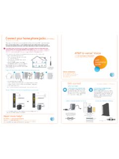
4 In this scenario, the two end users are User A and User B. User A is located at PBX A. PBX A is connected to Gateway 1 (SIP gateway). via a T1/E1. User B is located at a Cisco SIP IP phone . Gateway 1 is connected to the Cisco SIP IP phone over an IP network. The call flow is as follows: 1. User A calls User B. 2. User B answers the call . 3. User B hangs up. Cisco Unified IP phone 7960G and 7940G Administration Guide for Release (SIP). B-2 OL-7890-01. Appendix B SIP call Flows call Flow Scenarios for Successful Calls Figure B-1 Successful Setup and Disconnect SIP IP phone User A PBX A GW1 IP Network User B. IP. 1. Setup 2. INVITE. 3. call Proceeding 4. 100 Trying 5. 180 Ringing 6. Alerting 7. 200 OK. 8. Connect 9.
5 Connect ACK. 10. ACK. 2-way voice path 2-way RTP channel 11. BYE. 12. Disconnect 13. Release 14. 200 OK. 15. Release Complete 41724. Step Action Description 1. Setup PBX A to Gateway 1 call setup is initiated between PBX A and Gateway 1. Setup includes the standard transactions that take place as User A attempts to call User B. 2. INVITE Gateway 1 to Cisco SIP IP phone Gateway 1 maps the SIP URL phone number to a dial peer. The dial peer includes the IP address and the port number of the SIP-enabled entity to contact. Gateway 1 sends a SIP INVITE request to the address it receives as the dial peer, which, in this scenario, is the IP. phone . In the INVITE request: The IP address of the phone is inserted in the Request-URI field.
6 PBX A is identified as the call session initiator in the From field. A unique numeric identifier is assigned to the call and is inserted in the call -ID field. The transaction number within a single call leg is identified in the CSeq field. The media capability that User A is ready to receive is specified. The port on which the gateway is prepared to receive the RTP. data is specified. 3. call Proceeding Gateway 1 to PBX A Gateway 1 sends a call Proceeding message to PBX A to acknowledge the call Setup request. Cisco Unified IP phone 7960G and 7940G Administration Guide for Release (SIP). OL-7890-01 B-3. Appendix B SIP call Flows call Flow Scenarios for Successful Calls Step Action Description 4. 100 Trying Cisco SIP IP phone to The phone sends a SIP 100 Trying response to Gateway 1.
7 The Gateway 1 response indicates that the INVITE request has been received. 5. 180 Ringing Cisco SIP IP phone to The phone sends a SIP 180 Ringing response to Gateway 1. The Gateway 1 response indicates that the user is being alerted. 6. Alerting Gateway 1 to PBX A Gateway 1 sends an Alert message to User A. The message indicates that Gateway 1 has received a 180 Ringing response from the phone . User A hears the ringback tone that indicates that User B is being alerted. 7. 200 OK Cisco SIP IP phone to Gateway 1 The phone sends a SIP 200 OK response to Gateway 1. The response notifies Gateway 1 that the connection has been made. 8. Connect Gateway 1 to PBX A Gateway 1 sends a Connect message to the PBX A.
8 The message notifies PBX A that the connection has been made. 9. Connect ACK PBX A to Gateway 1 PBX A acknowledges Gateway 1's Connect message. 10. ACK Gateway 1 to Cisco SIP IP phone Gateway 1 sends a SIP ACK to the phone . The ACK confirms that Gateway 1 has received the 200 OK response. The call session is now active. 11. BYE Cisco SIP IP phone to Gateway 1 User B terminates the call session. The phone sends a SIP BYE. request to Gateway 1. The request indicates that User B wants to release the call . 12. Disconnect Gateway 1 to PBX A Gateway 1 sends a Disconnect message to PBX A. 13. Release PBX A to Gateway 1 PBX A sends a Release message to Gateway 1. 14. 200 OK Gateway 1 to Cisco SIP IP phone Gateway 1 sends a SIP 200 OK response to the phone .
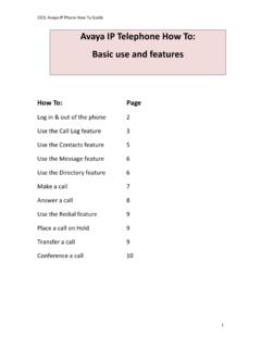
9 The response notifies the phone that Gateway 1 has received the BYE request. 15. Release Complete Gateway 1 to PBX A Gateway 1 sends a Release Complete message to PBX A, and the call session terminates. call Setup and Hold Figure B-2 illustrates a successful phone - call setup and call hold. In this scenario, the two end users are User A and User B. User A is located at PBX A. PBX A is connected to Gateway 1 (SIP gateway) via a T1/E1. User B is located at a Cisco SIP IP phone . Gateway 1 is connected to the Cisco SIP IP phone over an IP network. The call flow is as follows: 1. User A calls User B. 2. User B answers the call . 3. User B puts User A on hold. 4. User B takes User A off hold. Cisco Unified IP phone 7960G and 7940G Administration Guide for Release (SIP).
10 B-4 OL-7890-01. Appendix B SIP call Flows call Flow Scenarios for Successful Calls Figure B-2 Successful call Setup and Hold SIP IP phone User A PBX A GW1 IP Network User B. IP. 1. Setup 2. INVITE. 3. call Proceeding 4. 100 Trying 5. 180 Ringing 6. Alerting 7. 200 OK. 8. Connect 9. ACK. 10. Connect ACK. 2-way voice path 2-way RTP channel 11. INVITE (a=sendonly). 12. 200 OK. 13. ACK. No RTP packets being sent 14. INVITE (a=sendrecv). 15. 200 OK. 16. ACK. 137201. 2-way voice path 2-way VP. Cisco Unified IP phone 7960G and 7940G Administration Guide for Release (SIP). OL-7890-01 B-5. Appendix B SIP call Flows call Flow Scenarios for Successful Calls Step Action Description 1. Setup PBX A to Gateway 1 call setup is initiated between PBX A and Gateway 1.