Transcription of SIS - Emerson
1 Fisher FIELDVUE dvc6200 series digital ValveControllersContentsBefore You 1. Install the dvc6200 on the 2. Connect the Pneumatic 3. Connect the Electrical 4. Configure the Instructions for dvc6200 Instructions for DVC6200f Instructions for Solenoid Valve Health Start GuideD103556X012 dvc6200 digital Valve ControllersMarch 2018 This quick start guide provides installation and initial setup information for dvc6200 series digital valve controllersW9713 SISQ uick Start GuideD103556X012 dvc6200 digital Valve ControllersMarch 20182 Related DocumentsThe following documents include product specifications, reference materials, custom setup information, maintenanceprocedures.
2 And replacement part a copy of any of these documents is needed scan or click the appropriate code below, contact your Emerson salesoffice or Local Business Partner, or visit our website at or click code fordigital valve controllerfield supportFor information on installation and usage of dvc6200 series digital valve controllers, visit the Fisher channel on YouTube andsearch for HW1 Instruction Manual (D103409X012) dvc6200 HW2 Instruction Manual (D103605X012) dvc6200 SISDVC6200 SIS Instruction Manual (D103557X012)Safety manual for dvc6200 SIS (D103601X012)DVC6200fDVC6200f Instruction Manual (D103412X012)DVC6200pDVC6200p Instruction Manual (D103563X012)SISQ uick Start GuideD103556X012 dvc6200 digital Valve ControllersMarch 20183 Before You BeginDo not install, operate, or maintain a dvc6200 digital valve controller without being fully trained and qualified invalve, actuator, and accessory installation, operation, and maintenance.
3 To avoid personal injury or property damage,it is important to carefully read, understand, and follow all contents of this quick start guide, including all safetycautions and warnings. Refer to the appropriate instruction manual supplement listed below for hazardous areaapprovals and special instructions for safe use and installations in hazardous locations. If you have any questionsabout these instructions, contact your Emerson sales office or Local Business Partner before proceeding. CSA Hazardous Area Approvals - dvc6200 series digital Valve Controllers (D104203X012) FM Hazardous Area Approvals - dvc6200 series digital Valve Controllers (D104204X012) ATEX Hazardous Area Approvals - dvc6200 series digital Valve Controllers (D104205X012) IECEx Hazardous Area Approvals - dvc6200 series digital Valve Controllers (D104206X012)All documents are available from your Emerson sales office or at Contact your Emerson sales officeor Local Business Partner for all other approval/certification information.
4 WARNINGA void personal injury or property damage from sudden release of process pressure or bursting of parts. Before proceedingwith any Installation procedures: Always wear protective clothing, gloves, and eyewear to prevent personal injury or property damage. Do not remove the actuator from the valve while the valve is still pressurized. Disconnect any operating lines providing air pressure, electric power, or a control signal to the actuator. Be sure theactuator cannot suddenly open or close the valve. Use bypass valves or completely shut off the process to isolate the valve from process pressure.
5 Relieve process pressurefrom both sides of the valve. Use lock out procedures to be sure that the above measures stay in effect while you work on the equipment. Check with your process or safety engineer for any additional measures that must be taken to protect against processmedia. Vent the pneumatic actuator loading pressure and relieve any actuator spring precompression so the actuator is notapplying force to the valve stem; this will allow for the safe removal of the stem connector. WARNINGTo avoid static discharge from the plastic cover when flammable gases or dust are present, do not rub or clean the coverwith solvents.
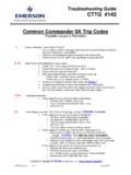
6 To do so could result in a spark that may cause the flammable gases or dust to explode, resulting in personalinjury or property damage. Clean with a mild detergent and water not use sealing tape on pneumatic connections. This instrument contains small passages that may become obstructedby detached sealing tape. Thread sealant paste should be used to seal and lubricate pneumatic threaded Start GuideD103556X012 dvc6200 digital Valve ControllersMarch 20184 Step 1 Install the dvc6200 on the ValveHousing VariationsThe dvc6200 housing is available in two different configurations, depending on the actuator mounting 1 shows the available 1.
7 Housing VariationsLINEAR, M8 ROTARY NAMUR, M6 SLOTS FORMOUNTING BOLTSHOUSING FOR LINEAR AND ROTARY ACTUATORS, FISHER 657 SIZE 30i - 70i, AND 667 SIZE 30i - 76iHOUSING FOR FISHER GX ACTUATORSHOLE FOR MOUNTING BOLTW9704W9703 INTEGRAL OUTPUTPRESSURE PORTG eneral Mounting GuidelinesIf ordered as part of a control valve assembly, the factory will mount the digital valve controller on the actuator andcalibrate the instrument. If you purchased the digital valve controller separately, you will need a mounting kit. Thefollowing procedures are general guidelines.
8 See the instructions that come with the mounting kit for detailedinformation on mounting the digital valve controller to a specific actuator magnet assembly material has been specifically chosen to provide a long term stable magnetic , as with any magnet, care must be taken when handling the magnet assembly. Another high powered magnetplaced in close proximity (less than 25 mm) can cause permanent damage. Potential sources of damaging equipmentinclude, but are not limited to: transformers, DC motors, stacking magnet Guidelines for use of High Power Magnets with PositionersUse of high power magnets in close proximity to any positioner which is operating a process should be avoided.
9 Regardlessof the positioner model, high power magnets can affect the positioner s ability to control the Start GuideD103556X012 dvc6200 digital Valve ControllersMarch 20185 Use of Magnetic Tools with the dvc6200 Magnetic Tip Screw Drivers Magnetic tip screw drivers can be used to work on the dvc6200 . However, they shouldnot be brought in close proximity to the magnet assembly (located at the back of the instrument) during processoperations. Calibrator Strap Magnets These are high power magnets used to hold 4-20 mA calibrators.
10 Normally, these calibrators would not be used while an instrument is controlling the process. High power magnetsshould be kept at least 15 cm (6 inches) from the The mounting instructions also apply to the DVC6215 remote mount feedback unit. As a general rule, do not use less than 60% of the magnet assembly travel range for full travel measurement. Performance willdecrease as the assembly is increasingly subranged. The linear magnet assemblies have a valid travel range indicated by arrows molded into the piece. This means that the hallsensor (the center point of the channel on the back of the dvc6200 housing) has to remain within this range throughout theentire valve travel.