Transcription of SKP75…U.. Air/Gas Ratio Controlling Gas Valve Actuator ...
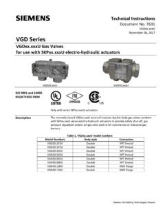
1 SKP Series Technical InstructionsDocument No. 1, 2005 Air/Gas Ratio Controlling Gas Valve Actuator with Safety Shutoff Function Only when assembled to Series Gas valves Description pressure regulating electro-hydraulic actuators are used in combination with series gas Valve bodies to provide shut-off and Air/Gas Ratio control for industrial and commercial burner applications. The controls the burner manifold gas pressure as a function of the combustion air pressure without the need for an additional constant gas pressure regulator. Since three functions: safety shut-off, constant pressure regulation, and Air/Gas Ratio control can be performed by a single Valve , fewer gas train components and fittings are required.
2 This significantly reduces both the size and weight of the gas train. In addition, smaller diameter gas valves can be used. The compact Actuator opens slowly and closes immediately when power is interrupted. The modular design allows the to be used in combination with all series gas valves bodies from 1/2-inch to 6-inch in size. The Actuator is easily mounted on the square flange of any Valve with four pre-mounted screws. A visible position indicator on the front of the Actuator displays the entire stroke of the Valve . A light indicates when the Actuator is powered. Features UL listed, FM approved, CGA and AGA certified, IRI approvable, ISO 9001 certified; European, Australian and Japanese approved versions available.
3 Safety shut-off function, pressure regulating function and Air/Gas Ratio control in one compact unit. Proof of Closure with Over Travel (POC) versions are available. Optional NEMA 4 protection. Simplifies commissioning and reduces start-up time. Maintains Air/Gas Ratio when the airflow is disrupted. Automatic compensation for combustion chamber back pressure fluctuations. No mechanical wear or play that causes drifting. Siemens Building Technologies, Inc. Technical Instructions Air/Gas Ratio Controlling Actuators Document No. 155-754 November 1, 2005 Page 2 Siemens Building Technologies, Inc. Features, Continued Compensation for air temperature fluctuations. Visual position indication.
4 "Power on" indication light Quick connect wiring terminals Optional adjustable auxiliary switch available. Excellent tracking characteristic. Modular design with 360o Actuator rotation for easy field wiring and installation. Low, VA power consumption. Application series actuators can be combined with 1/2-inch to 6-inch series gas Valve bodies. series gas valves must be ordered separately (See Instructions, P/N 155-512P25). If the combustion air pressure exceeds the permissible value of 12 or 20 WC (See Specifications), the pressure must be reduced by means of a pressure reducing T-fitting (See Figure 4, AGA78). Product Numbers Table 1. Product Number1 Operating Voltage Proof of Closure Switch 2 Auxiliary Switch 2 Type of Switch x SPDT x x SPDT SPDT 110 to 120 Vac x x SPDT SPDT 220 to 240 Vac 1.
5 European, CE certified models are available (see data sheet 7643). 2. Proof of closure and auxiliary switches cannot be field installed. Accessories Table 2. Product Number Description AGA66 Sealing gasket to provide NEMA 3, 3R, and 4 protection (for ) AGA78 Air pressure reducing T-fitting Specifications Agency approvals As safety shut-off Valve UL/429, FM/7400, ANSI C/I Agency marks apply only for actuators assembled with series gas Valve bodies. Power supply Operating voltage 110 to 120 Vac +10%-15% 220 to 240 Vac +10%-15% Operating frequency 50 to 60 Hz +6% Power consumption VA Duty cycle Continuous Air/Gas Ratio Controlling Actuators Technical Instructions Document No.
6 155-754 November 1, 2005 Siemens Building Technologies, Inc. Page 3 Specifications, Continued Operating environment Ambient operating temperature 5 F to 140 F (-15 C to 60 C) Mounting position Any position except upside down Maximum temperature of air and flue 140oF (60oC) gas at the control connections Maximum inlet gas pressure Same as Valve Physical characteristics Weight lb ( kg) Enclosure NEMA 1, 2, 5 and 12 for indoor use NEMA 3, 3R, and 4 with optional AGA66 gasket Dimensions See Figure 7 Specification for Valve bodies See gas Valve Technical Instructions P/N 155-512P25 Connections Conduit connection Two 1/2-inch NPSM threaded knock-outs Electrical connection Spring loaded terminals for 14 AWG wires Gas/air pressure connections 1/4" NPT (see Installation Notes)
7 Gas pressure test connection Hose barb with close-off screw Combustion chamber pressure test Hose barb with close-off screw connection Operating characteristics Output force 100 lb (450 N) Maximum stroke 1 inch (26 mm) Opening time for maximum stroke Varies with Valve size, 14 seconds for max. stroke. Closing time < seconds Control signal Reference input signal Combustion air pressure Control characteristic Integral action Operation/installation Setting range of gas to air pressure Ratio Pg/Pa from :1 to 9:1 Permissible pressures: Min. air pressure for accurate control " WC Max.
8 Air pressure: with setting Pg/Pa <2 20" WC Max. air pressure: with setting Pg/Pa >2 12" WC (with higher air pressures use AGA78) Min. downstream gas pressure for " WC accurate control Max. downstream gas pressure 40" WC at any Pg/Pa setting during operation NOTE: When the combustion chamber pressure Pc is connected, the above pressures should be considered pressure differentials Pg-Pc and Pa-Pc. Maximum gas pressure for leakage testing 20 psi Minimum time required for high to low 5 seconds fire load changes Minimum diameter of sensing lines 1/4" inside diameter Minimum distance between gas 5 times the pipe diameter sensing line and gas Valve outlet Auxiliary features Proof of closure switch Non-adjustable Capacity of auxiliary switch 6A/250 Vac resistive; 3A/120 Vac pilot duty Setting range of auxiliary switch 40% to 100% of stroke Technical Instructions Air/Gas Ratio Controlling Actuators Document No.
9 155-754 November 1, 2005 Page 4 Siemens Building Technologies, Inc. Operation (See Figure 1) Safety Shut-off Function The electro-hydraulic Actuator consists of a cylinder filled with oil, a piston containing an electric oscillating pump and a relief system. When power is supplied to the Actuator the relief system closes, and the pump moves oil from the reservoir into the pressure chamber. This action causes the piston to move downward in the cylinder, opening the gas Valve . When power to the Actuator is interrupted, the relief system opens and the gas Valve closes in less than seconds. A position indicator, visible through the transparent portion of the terminal cover, shows the entire stroke range of the Actuator .
10 A light, which is visible through the lower left transparent portion of the terminal cover, indicates when the Actuator receives power. An optional, non-adjustable SPDT proof of closure over travel switch signals the closed position after the gas Valve has closed. An optional SPDT auxiliary switch is adjustable between 40% and 100% of the stroke. The adjustment screw and scale are located on the right side in the terminal box, and are visible through the transparent portion of the terminal cover. Figure 1. Operation. Regulating Function During the burner pre-purge period, when the gas Valve is closed, only the air pressure acts on the regulator. This causes the air diaphragm to move to the left and close the regulating hydraulic bypass Valve .