Transcription of VA… Valve Actuator Assemblies with VKG Butterfly …
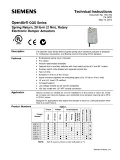
1 SCC Inc. Technical Instructions Document No. VA-1000. March 15, 2017. VA Series VA Valve Actuator Assemblies with VKG Butterfly valves Description VA Valve Actuator Assemblies include a Siemens SQM Actuator reliably mounted to a VKG Butterfly Valve to control the flow of natural gas, propane, butane, or air. Features Precision machined components enable the use of a solid shaft coupling Shaft coupling provides a positive connection between the Valve and Actuator without Actuator or Valve shaft damage Modular design enables field Actuator clocking in 90 increments Application VA Valve Actuator Assemblies mount an SQM33, SQM40, SQM45, or SQM50 Actuator to a VKG Butterfly Valve .
2 The VKG Valve and SQM Actuator are rigidly mounted with Siemens engineered brackets and couplings to ensure precise shaft alignment. VKG. technical instructions (CVLV-2000) provide sizing and additional Valve information. SCC Inc. Technical Instructions VA Series Document No. VA-1000. Product Part Numbers The following chart provides VA Valve Actuator assembly part number identification including an SQM33, SQM40, or SQM45 Actuator . Technical instructions for SQM33 (N7813), SQM40. (N7817), or SQM45 (N7814) actuators are available at VA 33 - N F - 200 - N4.
3 Valve Actuator Assembly Actuator 33 = (stepper, for use with LMV3 ). = ( sec, 135 Ohm/4-20 mA, high/low fire feedback). = ( sec, 4-20 mA, independent aux switch). = ( sec, 3-position, 3 independent aux switches). = (25 sec, 135 Ohm/4-20 mA, high/low fire feedback). = (25 sec, 4-20 mA, independent aux switch). = (25 sec, 3-position, high/low fire feedback). = (25 sec, high/low basic version). = (25 sec, 3-position, 3 independent aux switches). = (stepper, for use with LMV5 ). Voltage Blank = 120 Vac SQM40 or standard SQM33 or SQM45.
4 (220) = 220 Vac (not available for SQM33 & SQM45 actuators). Pipe Thread N = NPT. R = Rp Port Size F = Full Port M = Medium Port R = Reduced Port Pipe Size (mm) (inches). 050 = 1/2" Full Port only 075 = 3/4" Full Port only 100 = 1" Full Port & Medium Port 125 = 1-1/4" Full Port & Medium Port 150 = 1-1/2". 200 = 2". 250 = 2-1/2". 300 = 3". 400 = 4" NPT only Actuator NEMA Rating Blank = NEMA 12 SQM33 or SQM45; NEMA 4 SQM40. N4 = NEMA 4 SQM33 or SQM45. Page 2 SCC Inc. VA Series Technical Instructions Document No. VA-1000.
5 Product Part Numbers (continued). The following chart provides VA Valve Actuator assembly part number identification including an SQM50 Actuator . All VA Assemblies with an SQM5 Actuator and a VKG Butterfly Valve include the NEMA 4 kit. Technical instructions for SQM50 (155-517) actuators are available at VA 50 . 4 Z 3 - N F - 200. Valve Actuator Assembly Actuator 50 = SQM50. Torque / Timing 2 = 8 sec with 90 in-lb (90 stroke). 3 = 12 sec with 140 in-lb (90 stroke). 4 = 25 sec with 140 in-lb (90 stroke). Control Board Blank = (4-20 mA input).
6 A = (position proportional control). H = (0-135 input). K = (0-10 Vdc input). Z = (all inputs/outputs). Potentiometer Blank = (1000 , 90 ) on "G", "H", "K", or "Z" board; none on "A" board 3 = (1000 , 90 ) on "A" board only 7 = (1000 /1000 , 90 ). Voltage Blank = 120 Vac (220) = 220 Vac (24) = 24 Vac Pipe Thread N = NPT. R = Rp Port Size F = Full Port M = Medium Port R = Reduced Port Pipe Size (mm) (inches). 050 = 1/2" Full Port only 075 = 3/4" Full Port only 100 = 1" Full Port & Medium Port 125 = 1-1/4" Full Port & Medium Port 150 = 1-1/2".
7 200 = 2". 250 = 2-1/2". 300 = 3". 400 = 4" NPT only SCC Inc. Page 3. Technical Instructions VA Series Document No. VA-1000. Actuator Mounting Instructions In some cases, the Actuator may need to be removed from the Valve temporarily during piping. Additionally, the Actuator and bracket can be rotated relative to the Valve for wiring purposes. The instructions below and the exploded views in Figures 1 and 2 are a guide to proper disassembly and reassembly of a VA Valve Actuator assembly with a VKG Butterfly Valve .
8 SQM33/40/45 Actuators Disassembly 1. Start with the Valve at the closed / 0 position. 2. Remove the (4) #8 pan head screws (#2 phillips drive) and associated washers that fasten the Actuator to the large bracket. 3. Loosen the (2) M4 socket cap screws (3mm hex drive) that fasten the small bracket to the coupling. 4. Pull back on the small bracket and lift the Actuator off of the large bracket and out of the coupling. 5. Remove the (4) M6 flat head socket cap screws (4mm hex drive) from the large bracket and lift the bracket off of the 1/2 hex standoffs.
9 6. If more clearance is needed for piping, remove the (4) 1/2 hex standoffs using a crescent wrench. Also, remove the M4 socket cap screw (3mm hex drive) and lock washer fastening the coupling to the Valve shaft, and lift the coupling off of the Valve . If the Actuator is being rotated relative to the Valve for wiring purposes, remove the M4 socket cap screw (3mm hex drive) and lock washer fastening the coupling to the Valve shaft, and lift the coupling off of the Valve . Reassembly 7. If the (4) 1/2 hex standoffs were removed in step 6, thread them back into the threaded holes on top of the Valve and tighten with a crescent wrench.
10 If the coupling was removed in step 6, slide the coupling back over the Valve shaft. Insert the M4 socket cap screw and lock washer through the coupling and Valve shaft so that the coupling is in the desired position of the (4) clockable positions. The Valve should still be at the closed / 0 position. 8. Fasten the large bracket back onto the standoffs with the (4) M6 flat head socket cap screws (4mm hex drive) so that the overhanging section of the large bracket is on the opposite side of the coupling as the small bracket.