Transcription of VGD Series - SCC Inc.
1 Siemens AG Building Technologies Division VGD Series Technical InstructionsDocument No. 08, 2017 Gas Valves for use with electro hydraulic actuators ISO 9001 and 14000 REGISTERED FIRM Only with Series actuators Description The normally closed Series of modular double body gas valves combine with Series electro hydraulic actuators to provide safety shut off, gas pressure regulation and/or air gas ratio control for commercial or industrial gas burners. Table 1. model numbers Model Numbers Body style Connection Double NPT thread Double NPT thread Double NPT thread Double NPT thread Double NPT thread Double NPT thread Double ANSI flange Double ANSI flange Technical Instructions VGD Series Double Valves Document Number CC1N7631us November 08, 2017 Page 2 Siemens AG Building Technologies Division Features All Models UL listed, FM approved, CSA certified, IRI approvable, ISO 9001 and 14000 certified.
2 CE, Australian approved versions available inch NPT pressure taps on the inlet and outlet and between main valves (see Table 2 for details) Stainless steel mesh inlet filter protects the valve seat(s) as well as downstream components Dual stem guides ensure precise disc alignment and tight shut off Valves in connection with actuators open slowly and close rapidly models Compact double valve bodies consist of 2 safety shut off valves in Series . The first (inlet) valve has a flat valve disc applicable for safety shut off function only. The second (outlet) valve has a contoured valve disc for use with pressure regulating actuators ( , , ) A 1 inch NPT vent connection between the valves Each double valve requires 2 threaded mounting flanges ( ).
3 Each flange includes the necessary installation hardware (bolts, nuts and O ring). Each mounting flange has a inch NPT pressure tap. The flanges can be pre mounted onto the pipe, and then bolted onto the gas valve body. This feature eliminates the use of pipe unions and permits the gas valve assembly to be easily removed from a gas train Connecting pattern of the inch flanges are identical. This space permits any flange to be mounted to any valve body NOTE: valves and flanges must be ordered as separate items (see Tables 2 and 3). models Compact double valve bodies consist of 2 safety shut off valves in Series Each individual safety shut off valve has double seats to achieve high flow Patented seat construction with individual closing spring for each seat to assure reliable shut off and high close off pressure rating Full port vent line connection plates are available NOTE: valves and vent connection plates must be ordered as separate items (see Tables 2 and 3).
4 VGD Series Double Valves Technical Instructions Document Number CC1N7631us November 08, 2017 Siemens AG Building Technologies Division Page 3 Application All valves can be combined with any Series actuator. The actuator can be mounted while the valve is installed and under pressure. regulating actuators are applicable for both low and high supply gas pressure applications, eliminating excessive regulator inventories. Maximum pressure ratings vary with valve size (see Table 2). All valves perform these functions in combination with each of the following actuators: Safety shut off Safety shut off and constant pressure regulation or zero governor Safety shut off, pressure regulation and differential pressure air gas ratio control Safety shut off, pressure regulation and adjustable air/gas ratio control Since more than one function can be performed by a single valve, fewer components and fittings are required significantly reducing both the size and weight of the gas train.
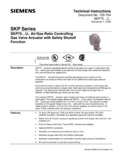
5 In addition, smaller diameter gas valves can be used. For details on valve sizing see the flow chart (figure 3). CAUTION: Do not oversize valves equipped with a regulating / / actuator. Oversizing may limit turndown and could cause oscillations. Technical Instructions VGD Series Double Valves Document Number CC1N7631us November 08, 2017 Page 4 Siemens AG Building Technologies Division Ordering information Gas valves and actuators are ordered separately. For additional actuator information, see the following technical instructions: 155 751P25 155 752P25 155 753P25 155 754P25 NOTE: The actuators have an operating temperature range of 14 F to 140 F ( 10 C to 60 C)! Table 2. Product numbers Product number Size Maximum operating pressure psi Close off pressure psi Capacity CFH Natural gas at P = 1" of test points, 1/4" NPT Valve body material Inlet Outlet *) 1" 20 30 600 Two inch andone 1 inch port between valvesAluminum *) 1 " 20 30 1200 Aluminum *) 1 " 20 30 1,850 Aluminum *) 2" 20 30 2,300 Aluminum 2 " NPT 10 75 3,880 1 1 Aluminum 3" NPT 10 75 5,370 1 1 Aluminum ** 4" flanged 10 30 9,680 1 1 Aluminum ** 6" flanged 10 30 17,490 1 1 Aluminum *) double valves require 2 threaded flanges for installation **) flanged valves must be installed using non metallic flange gaskets.
6 Gasket material must be chemically compatible with the fuel gas being used in the application and must be softer than the aluminum flange sealing surface. Acceptable gasket materials include but are not limited to: rubber, paper, and plastic. Observe flange bolt torque specifications as stated in the VGD40 installation instructions. Also refer to ANSI / ASME VGD Series Double Valves Technical Instructions Document Number CC1N7631us November 08, 2017 Siemens AG Building Technologies Division Page 5 Accessories Table 3. Accessories Part Number Description Notes Single 1" connecting flange with " port for 2 required per valve. Order separately Single 1 " connecting flange with " port for Single 1 " connecting flange with " port for Single 2" connecting flange with " port for 1 NPT vent connection plate for Each vent connection includes NPT test port, see Mounting instruction (74 319 0278 0) 1 NPT vent connection plate for 2 NPT vent connection plate for 2 NPT vent connection plate for AGA61 Manual adjusting throttle attachment AGA61 permits Series valves to be used as adjustable limiting orifice valves.
7 Once adjusted, the AGA61 has a provision to be sealed from tampering. AGA66 Sealing gasket to provide NEMA 3, NEMA 3R, and NEMA 4 protection. Gasket kit to mount Place between actuator and valve Increases degree of protection from IP54 to IP65 Refer to Mounting Instruction (74 319 0421 0) Technical Instructions VGD Series Double Valves Document Number CC1N7631us November 08, 2017 Page 6 Siemens AG Building Technologies Division Specifications Approvals Agency approvals/standards UL/429, FM/7400, CSA/ANSI C / I IRI approvable Agency marks apply only for Series gas valve bodies assembled with actuators. Operating environment Maximum operating pressure See Table 2 Maximum back pressure (differential) : 2 psi (150 mbar) : 4 psi (300 mbar) Close off pressure See Table 2 Permissible gas temperature 14 F to 140 F ( 10 C to 60 C) Permissible operating temperature 14 F to 140 F ( 10 C to 60 C) Use Siemens gas valves are in accordance with UL429.
8 The valve is used as: Safety shutoff valve (in connection with ) Control valve with safety shutoff function (in connection with , or ) Perm. mounting position 7631z01us/0815 Operating pressure See Type summary Types of gases Suitable natural gases, propane, butane and air For more information see Use. Strainer Built in, mesh size mm VGD Series Double Valves Technical Instructions Document Number CC1N7631us November 08, 2017 Siemens AG Building Technologies Division Page 7 Specifications Physical characteristics Body materials See Table 2 Weight See Tables 4 Connections Pipe connections NPT threads or ANSI class 150 flanges (see Table 2) Pressure and vent taps See Tables 2 and 3 Operation All gas valves are normally closed, two way valves.
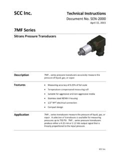
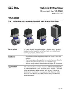
9 The valves have a standard, integral, stainless steel mesh filter ( mm) in the inlet to protect the downstream components against contamination. All valves have NPT ports for pressure test connection. A full size vent connection plate is available as an accessory for valves. See Table 2 and 3 for details on ports and vent connection plates. 1. Sectional view of double valves consist of two valves in Series . The first (inlet) valve has a flat valve disc suitable for the safety shut off function only. The second (outlet) valve has a contoured valve disc for stable regulating control and smooth release of gas. Technical Instructions VGD Series Double Valves Document Number CC1N7631us November 08, 2017 Page 8 Siemens AG Building Technologies Division Operation, continued 7631z53us/1215 Figure 2.
10 Second view of flange models double valves consist of two valves in Series . Each valve has a double seat to achieve high flow (see Figure 2). Closing springs: Each double seat uses one pair of springs. The spring forces act separately as closing forces on the individual valve seats. VGD Series Double Valves Technical Instructions Document Number CC1N7631us November 08, 2017 Siemens AG Building Technologies Division Page 9 Gas flow charts 100 2 3 4 5 7 1000 2 3 4 5 7 10000 2 3 4 5 7 100000 2 3 7 100 2 3 4 5 7 1000 2 3 4 5 7 10000 2 3 4 5 7 100000 2 7 100 2 3 4 5 7 1000 2 3 4 5 7 10000 2 3 4 5 7 100000 2 100 2 3 4 5 7