Transcription of SMAJ Series Pb - Littelfuse
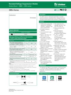
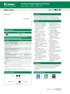
1 Transient Voltage Suppression Diodes 2015 Littelfuse , are subject to change without notice. Revised: 11/20/15 Surface Mount 400W > SMAJ seriesDescriptionAgency ApprovalsAGENCYAGENCY FILE NUMBERE230531 FeaturesMaximum Ratings and Thermal Characteristics (TA=25OC unless otherwise noted)ParameterSymbolValueUnitPeak Pulse Power Dissipation at TA=25 C by 10/1000 s Waveform ( )(Note 1), (Note 2), (Note 5)PPPM400 WPower Dissipation on Infinite Heat Sink at TL= Forward Surge Current, Single Half Sine Wave (Note 3)
2 IFSM60 AMaximum Instantaneous Forward Voltage at 25A for Unidirectional Only (Note 4) Temperature RangeTJ-65 to 150 CStorage Temperature RangeTSTG-65 to 175 CTypical Thermal Resistance Junction to LeadR JL30 C/WTypical Thermal Resistance Junction to AmbientR JA120 C/WNotes:1. Non-repetitive current pulse, per and derated above TJ (initial) =25 C per Fig. Mounted on copper pad to each Measured on single half sine wave or equivalent square wave for unidirectional device VF < for single die parts and VF< for stacked-die The PPPM of stacked-die parts is 600W and please contact Littelfuse for the detail stacked-die SMAJ Series is designed specifically to protect sensitive electronic equipment from voltage transients induced by lightning and other transient voltage devices are ideal for the protection of I/O Interfaces.
3 VCC bus and other vulnerable circuits used in Telecom, Computer, Industrial and Consumer electronic applications. 400W Peak pulse power capability at 10/1000 s waveform, repetition rate (duty cycle): Excellent clamping capability Typical IR less than 1 A when VBR min>12V For surface mounted applications to optimize board space Low profile package Typical failure mode is short from over-specified voltage or current Whisker test is conducted based on JEDEC JESD201A per its table 4a and 4c IEC-61000-4-2 ESD 30kV(Air), 30kV (Contact)
4 ESD protection of data lines in accordance with IEC 61000-4-2 EFT protection of data lines in accordance with IEC 61000-4-4 Built-in strain relief Fast response time: typically less than from 0 Volts to VBR min Glass passivated junction Low inductance High temperature to reflow soldering guaranteed: 260 C/40sec VBR @ TJ= VBR@25 C x (1+ T x (TJ - 25))( T:Temperature Coefficient, typical value is ) Plastic package is flammability rated V-0 per Underwriters Laboratories Meet MSL level1, per J-STD-020, LF maximun peak of 260 C Matte tin lead free Plated Halogen free and RoHS compliant Pb-free E3 means 2nd level interconnect is Pb-free and the terminal finish material is tin(Sn) (IPC/JEDEC )
5 SMAJ SeriesUni-directionalBi-directionalFunct ional DiagramBi-directional Uni-directional Cathode AnodeRoHSPbe3 DatasheetAdditional InfomarionResourcesSamplesTransient Voltage Suppression Diodes 2015 Littelfuse , are subject to change without notice. Revised: 11/20/15 Surface Mount 400W > SMAJ seriesElectrical Characteristics (TA=25 C unless otherwise noted)Part Number (Uni)Part Number (Bi)MarkingReverse Stand off Voltage VR (Volts)Breakdown Voltage VBR (Volts) @ ITTest CurrentIT (mA)Maximum Clamping Voltage VC @ Ipp (V)Maximum Peak Pulse Current Ipp (A)Maximum Reverse Leakage IR @ VR( A)Agency 1011.
6 11 7. 7. 7. 111. 0 0 0 0 parts without A , the VBR is 10% and VC is 5% higher than with A partsFor bidirectional type having VR of 10 volts and less, the IR limit is Voltage Suppression Diodes 2015 Littelfuse , are subject to change without notice. Revised.
7 11/20/15 Surface Mount 400W > SMAJ seriesI-V Curve CharacteristicsRatings and Characteristic Curves (TA=25 C unless otherwise noted)Voltage TransientsTimeVoltage Across TVSC urrent Through TVSV oltage or CurrentFigure 1 - TVS Transients Clamping WaveformFigure 2 - Peak Pulse Power Rating Curvetd-Pulse Width (ms)PPPM-Peak Pulse Power (kW) die,400W at 10x1000 s, 25 Cstacked-die, 600W at 10x1000 s, 25 CTJ initial = TambVcVBRVRIRITIppVUni-directionalVFVcVB RVRIRITIppVVcVBRVRIppIRITBi-directionalP PPM Peak Pulse Power Dissipation -- Max power dissipation VR Stand-off Voltage -- Maximum voltage that can be applied to the TVS without operationVBR Breakdown Voltage -- Maximum voltage that flows though the TVS at a specified test current (IT)
8 VC Clamping Voltage -- Peak voltage measured across the TVS at a specified Ippm (peak impulse current)IR Reverse Leakage Current -- Current measured at VRVF Forward Voltage Drop for Uni-directional continues on next Voltage Suppression Diodes 2015 Littelfuse , are subject to change without notice. Revised: 11/20/15 Surface Mount 400W > SMAJ series0204060801000255075100125175 Peak Pulse Power (PPP) or Current (IPP)Derating in Percentage %150TJ - Initial Junction Temperature ( C)Figure 3 - Peak Pulse Power Derating CurveIPPM- Peak Pulse Current, % IRSM005010 01501.
9 SecPeak ValueIPPMIPPM2TJ=25 CPulse Width(td) is definedas the point where the peak current decays to 50% of IPPM10/1000 sec. Waveformas defined by (ms)Half ValueIPPM( )Figure 4 - Pulse WaveformFigure 5 - Typical Junction Thermal Impedance ( C/W)T -Pulse Duration (s)PFigure 6 - Typical Transient Thermal Impedance010203040506070110100 IFSM-Peak Forward Surve Current (A)Number of Cycles at 60 HzFigure 7 - Maximum Non-Repetitive Forward Surge Current Uni-Directional OnlyRatings and Characteristic Curves (TA=25 C unless otherwise noted) (Continued)Cj (pF)VBR - Reverse Breakdown Voltage (V)
10 Uni/Bi-direc onalV=VRUni-direc onal V=0 VBi-direc onal V= Forward Current (A)VF-Peak Forward Voltage(V)Single dieStacked-dieFigure 8 - Peak Forward Voltage Drop vs Peak Forward Current (Typical Values)Transient Voltage Suppression Diodes 2015 Littelfuse , are subject to change without notice. Revised: 11/20/15 Surface Mount 400W > SMAJ seriesDimensionsPhysical ounce, gramCaseJEDEC DO-214AC Molded Plastic over glass passivated junctionPolarity Color band denotes cathode except BipolarTerminalMatte Tin-plated leads, Solderable per ParametersTemperature (T)Time (t)Ts(min)Ts(max)TLTPtsPreheattLtpRamp-u pCritical ZoneTL to TPRamp-downt 25 C to Peak25 CReflow ConditionLead free assemblyPre Heat- Temperature Min (Ts(min))150 C - Temperature Max (Ts(max))200 C- Time (min to max) (ts)