Transcription of Soldering Methods and Procedures for ROHS Compliant …
1 Page 1 of 5123333333333333333333333 OverviewThis document is intended to provide guidance formaking high quality solder connections of RoHSCompliant Vicor Power Modules to printed circuitboards. This application note applies to lead freesoldering of Vicor s RoHS Compliant modules; fornon-RoHS Compliant product, please seeapplication note Soldering Methods andProcedures for Vicor Power Modules Overview. Thefollowing provides an outline for appropriatesoldering Procedures and the evaluation of solderjoints to insure an optimal connection to the powermodule. Common Soldering defects will beexamined and direction will be provided fordetecting and handling them. Vicor smanufacturing facilities use the IPC-A-610 standardsfor establishing quality solder joints.
2 It isrecommended that manufacturing processes usingVicor modules refer to these same standards, whichcan be found, along with supportingdocumentation, at of a Good solder JointThe IPC-A-610 standard requires that solder fill atleast 75% of the barrel in order to insure a solidconnection. Ideally all connections should have a100% fill. In order to accomplish this, the solderapplied to both the barrel and the pin must exhibit aprocess known as wetting. Wetting occurs whenliquid solder on a surface is heated to the point thatit loses a significant amount of latent surface tensionand evenly coats the surface via capillary action(both cohesion and adhesion).During the Soldering process wetting can beidentified by an even coating of solder on the barreland pin.
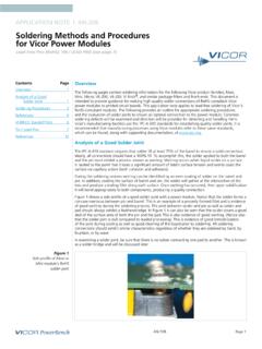
3 In addition to coating the surface of barreland pin the solder will gather at the intersection of the two and produce a trailing fillet along eachsurface. Once wetting has occurred, then upon solidification it will bond appropriately to bothcomponents, producing a quality 1shows a side profile of a good solder jointwith a power module. Notice that the solder forms aconcave meniscus between pin and barrel. This isan example of a properly formed fillet and isevidence of good wetting during the solderingprocess. The joint between solder and pin as well assolder and pad should always exhibit a featherededge. In Figure 1it can also be seen that the soldercovers a good deal of the surface area of both thepin and the pad. This is also evidence of goodwetting. (Notice also that the solder joint is dullcompared to leaded processing).
4 This is evidence ofgood immobilization of the joint during cooling aswell as good cleaning of the board prior tosoldering. All Soldering connections should exhibitsimilar characteristics regardless of whether they aresoldered by hand, by fountain, or by 1: Side profile of power module RoHS solder Methods and Procedures for Vicor ROHS Compliant Power Modulespage 2 of 5In examining a solder joint, be sure that there is nosolder connecting one pad to another. This is knownas a solder bridge and will be discussed ProceduresHand SolderingBefore Soldering , make sure that the PCB is cleanand free of debris, chemical residue, or liquid. It isnot recommended that additional flux other thanwhat is contained in the solder be used duringsoldering as it potentially leaves a residue thatcannot be removed without potentially damagingor compromising the power module.
5 Also, thepresence of these residues on the modules maycause harm or improper pins on Vicor modules are optimized to providea low resistance electrical connection. The finalmounting scheme for any module should bedesigned to minimize any potential mechanicalstress on the pins and solder joints. Modules withheat sinks or modules used in systems that aresubject to shock or vibration should use standoffs tominimize stress on the pins. It is not recommendedthat discrete wires or connectors be soldereddirectly onto a necessary for a good solder connection is pinprotrusion from the PCB. It is not possible to create agood solder joint without some protrusion of modulepins from the PCB. If the PCB is too thick to allowgood pin protrusion, consider using Vicor moduleaccessories such as sockets to allow propermounting.
6 See Vicor's accessory catalog for a complete list of moduleaccessories. Before Soldering , the module should bemechanically affixed or immobilized with respect tothe PCB to insure no movement during the solderingprocess. The standoffs can be used for this Power modules contain two types of pins,power pins (which deliver the power to the load andare typically sized according to the rated outputcurrent) and signal pins (which typically carry verylittle current and are of a uniform size across a givenproduct family). The larger the pin, the moresoldering time required to form an adequateconnection. In addition to the sizing of the pin, thetime required to create a robust connection will varydepending on several parameters: a) PCB thickness: The thicker the printed circuitboard, the more heat it is able to dissipate, and willrequire more Soldering ) Copper Trace area:Power pins require largecopper traces to minimize resistive power losses incarrying the power to the load.
7 Since the coppertends to conduct heat well, the actual size of thesecopper traces directly affect the amount of timenecessary to heat the PCB ) Copper Trace thickness:As above, the thicknessof the copper trace is a function of output current ofthe module, and has a direct impact on the amountof Soldering time. Typically PCB copper thickness isspecified in terms of weight per square foot, typically2oz. or 3oz. copper for current carrying planes. d) Soldering iron power:A higher power solderingiron can source more heat and thus take less time toheat a PCB trace. As a Soldering iron is heating apoint on the board, everything that is adjacent tothis point is being heated as well, including the Vicorpower module. A large copper trace, due to thefact that it conducts heat very well, will exhibit less ofa thermal gradient and thus a low power solderingiron will have to heat the whole trace to a highertemperature before the area close to the iron is hotenough to flow solder .
8 Due to the fact that the traceand board are both dissipating and conductingthermal energy, some irons may not have enoughpower to heat a trace to the temperature that willallow proper ) Tip temperature:Typical SAC-type solder melts at215-225 C. Pb-free Soldering requires a tiptemperature of about 800 F. A higher tiptemperature will bring the barrel and pin above themelting point of solder faster. However, a higher tiptemperature may cause damage to the pad,printed circuit board or module pin. f) Type of Lead-Free solder :The actual melting pointof the solder varies depending on the type of solderused and affects the necessary temperature of thepad and pin for flow. Vicor recommends SAC305 SnAgCusolder for use on Vicor power ) Tip size: A larger tip will be able to heat a largersurface area, thus lowering Soldering time.
9 Since there are so many factors that influencesoldering time, listing actual times is difficult. Ingeneral, it is recommended that the joint bepage 3 of 5examined post-process to insure a quality solderingjoint. If necessary, different parameters can then bevaried in order to insure a solid process. Thesoldering times listed in Table 1can be used as aguideline for establishing more application andprocess specific parameters. Below are somerecommendations for general not run tip temperature above 810 F. This willgreatly increase the risk of damaging the pads,traces, printed circuit board, or Vicor power with the printed circuit board manufacturerthat the boards are RoHS capable and for anyadditional recommendations in regard Apply the Soldering iron to one side of the pin andpad and apply the solder to the other, allowing theheat from the pin and pad to melt the solder .
10 Do notapply solder to the Soldering iron and subsequentlyattempt to transfer it to the pad and pin. Melting thesolder by applying it directly to the Soldering irondoes not guarantee adequate wetting on the jointand is not considered good not apply excessive pressure with the solderingiron to the printed circuit board, barrel, or pad. Thiscould result in breaking a trace, dislodging a barrelor damaging the PCB, which becomes noticeablysofter when not apply the Soldering iron to a connectionfor an extended period of time or damage to themodule could result. If the Soldering times exceedthe upper limit listed in Table 1, consider using alarger tip or a higher power Soldering Make sure PCB pads and holes are clean prior with no-clean flux may be used tofacilitate the tip of the Soldering iron clean and freefrom resin.