Transcription of SOLID CONE TECHNICAL DATA SPRAY NOZZLES
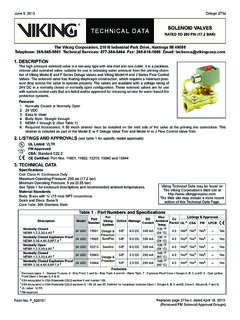
1 SOLID CONE SPRAY NOZZLESTECHNICAL DATAThe Viking Corporation, 210 N Industrial Park Drive, Hastings MI 49058 Telephone: 269-945-9501 TECHNICAL Services: 877-384-5464 Fax: 269-818-1680 Email: No. F_030789 Rev 1 of 131. DESCRIPTIONV iking Model A-2, A-2X, B-2, C-2, and D-2 SOLID Cone SPRAY NOZZLES are non-auto- matic pattern, open, directional discharge SPRAY NOZZLES . The SPRAY nozzle units feature two-piece construction consisting of a cast bronze body and threaded insert. The insert determines the included angle of discharge and the body construction provides a uniform distribution throughout the discharge pattern. When spraying, the nozzle discharge forms a SOLID , cone-shaped SPRAY pattern meeting the requirements for medium- and high-veloc-ity water SPRAY dust plugs are available to prevent foreign material from entering the open end of the SPRAY nozzle .
2 They are designed to blow off when the system piping is LISTINGS AND APPROVALScULus Listed: Category VGYZFM Approved: Water- SPRAY SystemsNYC Approved: Calendar Number 219-76-SA, Bulletin No. 16, Vol. LXINOTE: International approval certificates are available upon NOZZLES are approved for use in medium- and high-velocity water spraysystems. Refer to the Approval Charts on pages 4-5 and Design Criteria onpage 6 for cULus and FM approval requirements that must be TECHNICAL DATAS pecifications:Available since water inlet is at a 90 angle to the nozzle outlet. The smallest nozzle passage is 1/4 (6 mm) for Part Nos. 05133 AAJ through 05134 AJN; 11/32 (9 mm) for Part Nos. 05135 AAJ through 05135 AJN; 3/8 (10 mm) for Part Nos. 19505J through 19505JN; and 7/16 (11 mm) for Part Nos. 19506AJ through bodies are permanently marked with the model inserts are permanently marked with the angle of discharge and are available in SPRAY angles of 30 , 60 , 90 , 120 , and 140 Refer to pages 7-13 for SPRAY nozzle water distribution size: 1/2 (15 mm) NPT male thread is standardNominal K-Factors: Refer to the Approval ChartsDust Plugs (Optional):Red Polyethylene Cap: 1 (25 mm) deepRated for a continuous temperature of 220 F (104 C).
3 SPRAY nozzle Material Standards:Body Casting: Brass UNS-C84400 Insert: Brass UNS-C36000 Ordering Information: (Also refer to the current Viking price list.)Order Model A-2, A-2X, B-2, C-2, and D-2 SOLID Cone SPRAY NOZZLES by selecting the appropriate part number from the Approval Charts. Available Finishes: Brass or Electroless Nickel. Refer to the Approval ChartsFor example, SPRAY nozzle Model A-2 (VK740) with a K-Factor, a 30 SPRAY angle, and a Brass finish = Part No. 05133 AAJDust Plugs (Optional): Dust plugs are used to prevent the depositing of foreign materials in the waterway, which could interfere with the discharge of the SPRAY NOZZLES . The plugs are designed to blow off when the system piping is Number 02409A for use with SPRAY nozzle Part Nos. 05133 AAJ through Number 02410A for use with SPRAY nozzle Part Nos.
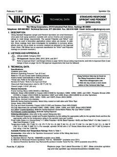
4 19505AJ through TECHNICAL Data may be found on The Viking Corporation s Web site at Web site may include a more recent edition of this TECHNICAL Data Cone SPRAY NozzlesSpray nozzle Dust Plug(Added C&D NOZZLES , UL only) SOLID CONE SPRAY NOZZLESTECHNICAL DATAThe Viking Corporation, 210 N Industrial Park Drive, Hastings MI 49058 Telephone: 269-945-9501 TECHNICAL Services: 877-384-5464 Fax: 269-818-1680 Email: No. F_030789 Rev 2 of 134. INSTALLATIONWARNING: Viking Model A-2, A-2X, B-2, C-2, and D-2 SOLID Cone SPRAY NOZZLES are manufactured and tested to meet the rigid requirements of the approving agency. The NOZZLES are designed to be installed in accordance with recognized installation stand-ards. Deviation from the standards or any alteration to the nozzle after it leaves the factory including, but not limited to: painting, plating, coating, or modification, may render the unit inoperative and will automatically nullify the approval and any guarantee made by The Viking Approval Charts on pages 4-5 show listings and approvals of Model A-2, A-2X, B-2, C-2, and D-2 SPRAY NOZZLES for use on water SPRAY systems.
5 The charts show listings and approvals available at the time of printing. Other approvals are in process. Check with the manufacturer for any additional approvals. A. SPRAY NOZZLES are to be installed in accordance with the latest edition of Viking TECHNICAL data, the latest published standards of NFPA, FM Global, LPCB, APSAD, VdS or other similar organizations, and also with the provisions of gov-ernmental codes, ordinances, and standards whenever applicable. The use of Model A-2, A-2X, B-2, C-2, and D-2 SPRAY NOZZLES may be limited due to occupancy and hazard. Refer to the Authority Having Jurisdiction prior to SPRAY NOZZLES are installed on fixed fire protection systems, such as deluge systems, where total flooding is Handle SPRAY NOZZLES with care. They must be stored in a cool, dry place in their original shipping container.
6 Never install a SPRAY nozzle that has been dropped or Corrosion-resistant SPRAY NOZZLES must be installed when subject to corrosive atmospheres. When installing corrosion resistant NOZZLES , take care not to damage the corrosion resistant coating. E. SPRAY NOZZLES must be installed after the piping is in place to prevent mechanical damage. F. Before installing, be sure to have the appropriate model, with the correct K-Factor and SPRAY angle. SPRAY nozzle bodies are permanently marked with the model number. All inserts are permanently marked with the angle of discharge and model. 1. Apply a small amount of pipe-joint compound or tape to the external threads of the SPRAY nozzle only, taking care not to allow a build-up of compound inside the Install the nozzle on the fixed piping using a standard crescent wrench. Take care not to over-tighten or damage the SPRAY nozzle .
7 G. SPRAY NOZZLES must be protected from mechanical damage. Where open SPRAY NOZZLES are used, care must be taken to prevent foreign materials from entering the orifice. Foreign materials may accumulate and restrict or plug the waterway and may prevent proper operation of the SPRAY nozzle . H. Install dust plugs (if used): After installing the SPRAY nozzle unit, press the dust cover over the end of the nozzle OPERATIONM odel A-2, A-2X, B-2, C-2, and D-2 SOLID Cone SPRAY NOZZLES are designed to apply cooling water to exposed vertical, horizontal, curved, and irregular shaped surfaces to allow cooling of objects externally when exposed to an adjacent fire. Cooling is done to prevent objects from absorbing heat that could cause structural damage and possible spread of fire to the protected object. In some applications, Model A-2, A-2X, B-2, C-2, and D-2 SPRAY NOZZLES may be applied to control or extinguish fire of the protected area (depending on water design application density).
8 6. INSPECTIONS, TESTS AND MAINTENANCENOTICE: The owner is responsible for maintaining the fire protection system and devices in proper operating condition. For minimum maintenance and inspection requirements, refer to the NFPA standard ( , NFPA 25) that describes care and maintenance of sprin-kler systems. In addition, the Authority Having Jurisdiction may have additional maintenance, testing, and inspection requirements that must be SPRAY NOZZLES must be inspected on a regular basis for corrosion, mechanical damage, obstructions, paint, etc. Where open SPRAY NOZZLES are installed, verify that foreign materials (such as dust, dirt, etc.) do not restrict or plug the waterspray. The fre-quency of inspections may vary due to corrosive atmospheres, water supplies, and activity around the device. It is also recom-mended that outdoor installations of SOLID Cone SPRAY NOZZLES with dust plugs be periodically inspected, during freezing weather conditions, for the presence of ice buildup from trapped condensate which could effect the proper release of the SPRAY NOZZLES that have been painted or mechanically damaged must be replaced immediately.
9 NOZZLES showing signs of corrosion shall be tested and/or replaced immediately as required. When replacing SPRAY NOZZLES , use only new SPRAY NOZZLES . 1. Using a standard crescent wrench, remove the old SPRAY nozzle and install the new unit. Care must be taken to ensure that the replacement SPRAY nozzle is the proper model with the correct K-Factor. SPRAY nozzle bodies are permanently marked with the model number. All inserts are permanently marked with the angle of discharge and model. C. The SPRAY nozzle discharge pattern is critical for proper fire protection. Therefore, nothing should be hung from, attached to, or oth-erwise obstruct the discharge pattern. All obstructions must be immediately removed or, if necessary, additional NOZZLES CONE SPRAY NOZZLESTECHNICAL DATAThe Viking Corporation, 210 N Industrial Park Drive, Hastings MI 49058 Telephone: 269-945-9501 TECHNICAL Services: 877-384-5464 Fax: 269-818-1680 Email: No.
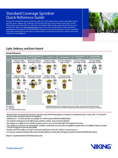
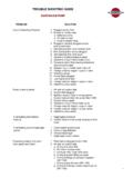
10 F_030789 Rev 3 of 13 Figure 1: SPRAY nozzle DimensionsTABLE 1: SPRAY nozzle DIMENSIONSSINABCDEFGHVK740-VK7641-7/8 (48 mm)7/8 (22 mm)1/2 (13 mm)1-5/8 (41 mm)13/16 (21 mm)5/16 (8 mm)1-17/64 (32 mm)1-11/16 (43 mm)VK770-VK7842-1/16 (52 mm)1 (25 mm)5/8 (16 mm)2-3/16 (56 mm)1 (25 mm)3/8 (10 mm)1-17/32 (39 mm)2 (51 mm) SOLID CONE SPRAY NOZZLESTECHNICAL DATAThe Viking Corporation, 210 N Industrial Park Drive, Hastings MI 49058 Telephone: 269-945-9501 TECHNICAL Services: 877-384-5464 Fax: 269-818-1680 Email: No. F_030789 Rev 4 of 13 Approval Chart 1 Model A-2, A-2X, B-2, C-2, and D-2 SPRAY NOZZLES - Brass FinishPart Number1 SINN ominal K-FactorAngleListings and Approvals3 (Refer also to Design Criteria on page 6.)Part Number1 SINN ominal K-FactorAngleListings and Approvals3 (Refer also to Design Criteria on page 6.)