Transcription of SOLID MECHANICS DYNAMICS TUTORIAL – FORCED …
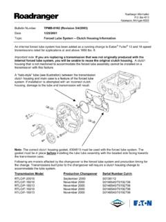
1 1 SOLID MECHANICS DYNAMICS TUTORIAL FORCED VIBRATIONS This work covers elements of the syllabus for the Engineering Council Exam D225 DYNAMICS of Mechanical Systems and C105 Mechanical and Structural Engineering. On completion of this TUTORIAL you should be able to do the following. Define a FORCED vibration in general terms. Explain the whirling of shafts and solve problems. Solve problems involving mass spring damper systems. Analyse the case of a harmonic disturbing force. Analyse the case of a harmonic disturbance of the support. Analyse the frequency response for the same. Define and use phasors. This TUTORIAL covers the theory of FORCED vibrations. You should study the TUTORIAL on free vibrations before commencing.
2 CONTENTS 1. INTRODUCTION 2. WHIRLING OF SHAFTS Self Assessment Exercise 3. OTHER FORCED VIBRATIONS Harmonic disturbing force Phasor representation Frequency response diagrams Self Assessment Exercise Harmonic movement of the support Magnification factor Self Assessment Exercise Transmissibility 1. INTRODUCTION In the TUTORIAL on damped oscillations, it was shown that a free vibration dies away with time because the energy trapped in the vibrating system is dissipated by the damping.
3 The equation for the displacement in a damped oscillation was derived and given as () tcostn Cex = is the damping ratio and n the natural angular frequency. The following cases were described. When >1 we have an over damped system. When =1 we have a critically damped oscillation. When < 1we have a damped oscillation that dies away with time. When = 0 we have a system with no damping and a steady oscillation occurred It might be inferred from this pattern that if <0 we get an oscillation that grows with time. The diagram illustrates this pattern. Figure 1 In order for the damping ratio to be less than zero, that is, to be negative, we would have to have the opposite of damping, something that puts energy into the system instead of taking it out. As the energy is added to the system the amplitude grows and grows.
4 The energy is added by an outside source and such oscillations are called FORCED , (the object of this TUTORIAL ). A good example of such an oscillation is a child on a swing. If nothing is done, friction will make the swing come to a halt. If someone gives the swing a small push at he start of each swing, energy is added to the system and the swing goes higher and higher. This phenomenon is also known as excitation. In engineering, many structures are prone to vibrate when excited at or near the natural frequency. A good example is what happens to a car when the wheels are out of balance or when you drive along a corrugated surface. If the disturbance is close to the natural frequency of the suspension system the vehicle might bounce out of control. Vehicles are fitted with dampers to prevent this.
5 The wind blowing around chimney stacks, cooling towers and suspended cables can excite them into catastrophic oscillations. The first case to be examined here is that of whirling shafts. 2 3 2. WHIRLING OF SHAFTS When a shaft rotates, it may well go into transverse oscillations. If the shaft is out of balance, the resulting centrifugal force will induce the shaft to vibrate. When the shaft rotates at a speed equal to the natural frequency of transverse oscillations, this vibration becomes large and shows up as a whirling of the shaft. It also occurs at multiples of the resonant speed.
6 This can be very damaging to heavy rotary machines such as turbine generator sets and the system must be carefully balanced to reduce this effect and designed to have a natural frequency different to the speed of rotation. When starting or stopping such machinery, the critical speeds must be avoided to prevent damage to the bearings and turbine blades. Consider a weightless shaft as shown with a mass M at the middle. Suppose the centre of the mass is not on the centre line. Figure 23 Figure 2 When the shaft rotates, centrifugal force will cause it to bend out. Let the deflection of the shaft be r. The distance to the centre of gravity is then r + e. The shaft rotates at rad/s. The transverse stiffness is kt N/m The deflection force is hence F = kt r The centrifugal force is M 2(r + e) Equating forces we have ()()1 e 1 e r Mk shown thatbeen already hasIt kM 1keM rkeM krM kerM r which from erM rkn2n22n22ntt2t2t2t2t22t = == =+=+=+= From this we see that when n= r = e/0 which is infinity.
7 This means that no matter how small the imbalance distance e is, the shaft will whirl at the natural frequency. Balancing does help but can never be perfect so whirling is to be avoided on the best of machines. The frequencies at which whirling occurs are calculated by the same methods as for transverse vibrations of beams and the derivation is not given here. SIMPLY SUPPORTED The ends are free to rotate normal to the axis ( self aligning bearings) 42wLgEI n 2 f =where n is the mode and must be an integer 1, 2, 3 .. Figure 3 FIXED ENDS ( fixed bearings or chucks) The lowest critical speed is the higher critical speeds are given by 42wLgEI21n2 f +=where n = 2, 3.
8 Note that the lowest speed almost corresponds to n = 1 Figure 4 CANTILEVER ( chuck at one end and free at the other) The lowest critical speed is 42wLgEI21n2 f =where n = 2, 3 .. Note that the lowest speed almost corresponds to n = 1 Figure 5 WORKED EXAMPLE A shaft is 30 mm diameter and 4 m long and may be regarded as simply supported. The density is 7 830 kg/m3. E = 205 GPa. Calculate the first three critical frequencies. SOLUTION The essential information is d = m L = 4 m = 7830 kg/m3 E = 205 GPa First calculate the distributed weight w by calculating the weight of 1 m length. rev/s 3 x be ouldfrequncy w themode third theup shaft took theIfrev/s 2 x be ouldfrequncy w themode second theup shaft took theIfrev/s x 10 x x 10 x 205 x ffrequency.
9 Funamental thecalculate Now m 10 x x 64 dIN/m x 10 x x 7830 gA x x Weight m 10 x 1A x Volume m 10 x x 4 d A 2249-94n49-446-36-26-22================ 4 WORKED EXAMPLE A light shaft carries a pulley at the centre with its centre of gravity on the centre line. The shaft is supported in self aligning bearing at the ends. The shaft deflects mm under the static weight of the shaft. Determine the lowest critical speed. SOLUTION The frequency corresponds to that of a simply supported beam so Hz 1xg2 1fs=== The critical speed is 60 x = 1338 rev/min WORKED EXAMPLE The shaft in the previous example has a distributed weight of 40 N/m and the bearings are m apart.
10 The flexural stiffness is 4500 N m2. What is the critical speed taking into account the distributed mass? SOLUTION The frequency due to the distributed weight only is x 404500 x 2 f 44=== N = 60f = 2176 rev/min The critical speed is N is found from 22222122176113381N1N1N1+=+= Hence N = 1140 rev/min WORKED EXAMPLE A steel wire 2 mm diameter is held between chucks 1m apart. The wire weighs N/m. The flexural stiffness is N m2. Calculate the first two critical speeds critical speed. SOLUTION The lowest frequency due to the distributed weight only is 91 x x 44=== N = 60f = 540 rev/min The second critical speed is x x wLgEI21n2 f4242= += += N = 60 = 1489 rev/min 5 6 SELF ASSESSMENT EXERCISE 1.