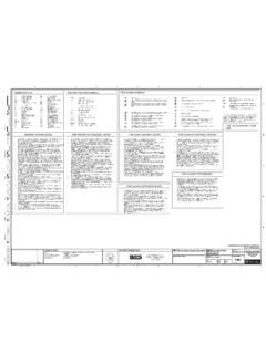
Transcription of SPECIFICATIONS FOR FIRE HYDRANT & SPRINKLET SYSTEM.
1 1 SPECIFICATIONS FOR FIRE HYDRANT & SPRINKLET SYSTEM. 1. General. Work under this subhead is time-bound and has t be completed within the time limit set in the tender. Work shall be executed in accordance with an agreed schedule which shall be submitted by the tenderers along with offer and agreed to by owners. Scope of work. The scope of work in this subhead shall consist of furnishing all labour, materials, equipment and appliances necessary and required to completely do all work relating to the supply, installation, testing & commissioning of Fire Fighting System as described herein after and shown on the drawings. The scope of work in general shall included the following. i) Fire Fighting Pumps & Accessories and related electrical works. ii) External & Internal Fire HYDRANT System. iii) Sprinkler system in entire building. iv) Hand Appliances. Without restricting to the generality of the foregoing, the work shall include the following: A HYDRANT System covering the entire complex and consisting of the following : A.
2 Three number of Pump One number Main electric end suction pump of 2280 LPM at 60 M head, one number a Diesel Standby split casing Pump for HYDRANT System of 2280 LPM at 60 M head and Jockey Pump for System pressurization of 180 LPM at 60 M. head. B. Other piping system ancillaries such as Suction and Delivery Headers, Air Vessel, Pressure Gauges, Pressure Switches, Pump Panel etc. as required. C. External HYDRANT Ring Main of 150mm dia with single headed Yard Hydrants, RRL Hoses, Branch Pipes etc. all housed in a Hose Box. D. Internal HYDRANT system where required with single headed landing valves on each floor accompanied by 1 number swinging type Hose Reel, 2 numbers RRL Hoses, 1 number of Branch Pipe etc. all housed in the niche. Bidder shall provide front frame with shutter for niche. E. Sprinkler system for entire building. F. Hand appliance as per Bill of Quantities. G. To obtain the approval of the relevant drawings before actual installation at site and to get the complete installation inspected and passed by the concerned authorities, as may be necessary as per local bye-laws.
3 (any fee payable to the local bodies. 2 Contractor s Experience. Contractors shall engaged specialist agency only for this work of Fire Fighting systems. The selected specialist agency must have sufficient experience in the execution of turnkey projects as specified. Contractor must submit with the tender a list of similar jobs carried out by him as required along with the name of works, name and address of clients, year of execution, capacity of plant and value of work. Technical Information. Contractor shall submit along with the tender copies of detailed SPECIFICATIONS , cuts, leaflets and other technical literature of equipment and accessories offered by him. Contractor s attention is specially invited to the special conditions and other clauses in the agreement which required the contractor to :- a. Submit detailed shop drawings. b. Use material of specific makes and brands c.)
4 Obtain all approvals from Fire Fighting authorities. d. Execute the entire work on a turn-key basis so as to provide a totally operating plant. Exclusions. Work under the contract does not include the following work. Electrical cable up to incoming motor control centre. Site Accessibility. The equipments are to be located in pump house located within the Service block. The equipment must be carried from the goods receiving station to the site in an extremely careful manner to prevent damage to the equipment building or existing services. Contractor must visit the site and familiarize himself with above problems to ensure that the equipment offered by him are of dimensions that they can be carried and planed in position without any difficulty. 3 Approvals. The contractor shall prepare all submission drawings and obtain all approvals of fire fighting works from fire fighting authorizes.
5 System Description. The HYDRANT System shall comprise of AC motor driven pump set, standby diesel pump set, jockey pump set for pressurization and fire booster pump with all required accessories including valves, special fittings, instrumentation, control panels and any other components required to complete the system in all respects. The HYDRANT System shall be semi automatic in action and shall be laid covering the entire area externally and all the floors internally with independent piping system for Sprinkler System, a separate piping system shall be installed. The HYDRANT System shall be kept pressurized at all times. The proposed Hockey Pump shall take care of the leakages the system, pipe lines and valve glands. The pressure in the HYDRANT pipe work shall be kept constant at 6 Kg/cm2. In the event of fire when any of the HYDRANT valve in the network is opened, the resultant fall in header pressure shall start the AC motor driven fire pump through pressure switches automatically.
6 There shall be one Diesel Engine Driven pump as standby for both HYDRANT system. In case of failure of electricity or failure of Electric Pump to start on demand, the standby Diesel Pump shall automatically take over. However, shutting down of the pump set shall be manual except for the Jockey Pump which shall start and stop automatically through pressure switches. In addition to auto start arrangements, the main pump shall also have an over-riding manual starting facility by push bottom arrangement. The ping for the HYDRANT system in the yard shall be laid in soil 1 Metre deep or in rectangular trench. The pipe laid in soil shall be protected as specified. The yard hydrants shall be placed at a regular spacing of 45m centre to centre. The following accessories are proposed near each yard HYDRANT . i) One no. gunmetal single headed HYDRANT vales. ii) Two nos. RRL Hoses of size 63mm dia x15m long.
7 Iii) One nos. gunmetal Branch pipe. Gun metal HYDRANT valve, RRL hose and gunmetal branch pipe will be accommodated in a aluminium hose box mounted on brick pedestals. The Internal HYDRANT System (Wet Risers) shall be provided at points as indicated on the drawing on each floor. 4 The HYDRANT point shall be directly tapped from the Riser pipes, and shall be furnished with required accessories such as i) One no. gunmetal single headed HYDRANT valves. ii) Two nos. RRL Hoses of size 63mm dia x 15m long. iii) One no. first aid Dunlop hose reel full swinging type 20mm dia x 30m long. iv) One nos, gunmetal Branch pipe. The HYDRANT risers shall be terminated with air release vale at the highest points to release the trapped air in the pipe work. At each tapping from the Riser a Orifice Plate shall be located in the lower floors to reduce the pressure. An overhead tank 20000 litres capacity will be connected to the fire HYDRANT system.
8 Sprinkler system shall be distributed entire building so as to cover 12-12 area with one sprinkler Sprinkler risers shall be provided with instantaneous control valve with alarm gang. An overhead tank of 20000 litres capacity with makeup line will be connected to sprinkler riser at basement (overhead tank is excluded from scope of work) A suitable drainage arrangement with bye-ass valve shall be provided to facilitate maintenance f sprinkler pipe work. To compensate for slight losses of pressure in the system and to provide an air cushion for counteracting pressure surges/water hammer in the underground pipe work Air Vessels shall be furnished in the pump room ear fire pumps. The air vessel shall be normally partly full of water and the remaining being filled with air which shall be under compression when the system is in normal operation. The entire Wet Riser and external HYDRANT Ring Main System shall be fed from the water supply (Static Water Tank) and pump room to be provided by the others.
9 GENERAL SPECIFICATIONS . Pipes and Fittings. Pipes for Wet Riser system shall be of GI pipe (Heavy Duty).Pipes upto 150mm dia shall be GI and conform to IS-1239. Pipes with dia 200mm and above (6mm thick) shall be MS and form to IS-3589. All pipes shall be marked. Fittings for black steel pipes shall be malleable iron suitable for welding or approved type cast iron fittings with tapered screwed threads. Jointing Joint for black steel pipes and fittings shall e metal-to-metal tapered thread or welded joints. A small amount of red lead may be used for lubrication and rust prevention in threaded joints. Joints between or black steel pipes, valves and other apparatus, pumps etc. shall be made with or flanges with appropriate number of bolts. Flanged joints shall be made with 3mm thick insertion rubber gasket. 5 Note : Joints for pipes and fittings upto 50mm diameter shall be threaded joints using Teflon Tape or equivalent bonding tape on the threads.
10 Joints for pipe and fittings above 50mm diameter shall be welded joints. Pipe Protection. a) All pipes in underground masonry trenches/service tunnels, above ground and in exposed locations shall be painted with one coat of red oxide primer and two or more coats of synthetic enamel paint of approved shade. b) Pipes in wall chases shall be protected from corrosion by 2 coats of bituminous paints. c) Protection of Underground pipes. The underground steel pipes shall be protected by coating and wrapping. The coating and wrapping shall be done, in general as per IS:10221-1982. It specified in Bill of Quantities, the proprietary pipe production system shall be provided as per the Manufacturers recommendation. The proprietary system shall be of approved make. Installation of Pipes. All pipes shall be adequately supported from ceiling or walls by structural clamps fabricated from structural rods, channels, angles and flats.