Transcription of ST5484E 2-WIRE SEISMIC VIBRATION TRANSMITTER
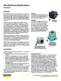
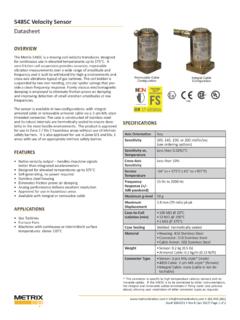
1 ST5484E 2-WIRE SEISMIC VIBRATION TRANSMITTERI nstallation ManualDOC# M9162 REV Y (Feb 2016)1. OVERVIEW The ST5484E SEISMIC VIBRATION Transmit-ter combines a VIBRATION sensor and signal conditioner in a single package for sensing machinery VIBRATION level and transmitting a proportional 4-20 mA signal directly to PLCs, DCSs, monitors, and computers. Versions with 2 wires, 4 wires, terminal blocks, or MIL-type connector are TRANSMITTER has no moving parts and is encapsulated in a stainless steel housing. Each TRANSMITTER is factory calibrated to the sensitivity marked on the label. An optional dynamic signal output can be to Metrix Datasheet 1004457 for specifications, ordering information, and outline MOUNTINGIt is important to solidly mount the transmit-ter body to the machine surface. Refer to section 6 on transducer placement. Differ-ent machine preparations are required for the two basic TRANSMITTER mounting styles; NPT (National Pipe Thread) and machine thread (UNF and Metric).
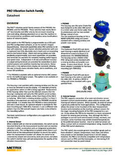
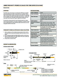
2 Transmitters with the NPT type mounting stud are secured by the thread engagement and the base of the TRANSMITTER does not contact the machine surface. Transmitters with the machine thread studs must contact the machine surface. The base of the TRANSMITTER must make square and direct contact. This re-quires preparing the surface of the machine with a 1 1/2 inch counter bore (surfacing tool). This tool can be used with a portable 1180 Flying Leads2-Pin Terminal Block4-Pin Terminal Block2-Pin MIL ConnectorDoc# M9162 REV Y (July 2016) Page 2 of 12 drill equipped with a magnetic base but care must be taken so that the tapped and threaded hole is perpendicular to the machined surface. The TRANSMITTER must make contact all the way around its base surface. Contact Metrix for more detailed counter bore installing a TRANSMITTER with a standard 1/4 inch NPT stud, drill a hole using a 7/16 inch bit, 5/8-7/8 inch deep.
3 Then tap using a 1/4 - 18 NPT (tapered pipe tap). Hand-tighten the TRANSMITTER and then turn an additional 1 to 2 turns using a wrench on the wrench flats. Do not use a pipe wrench. A pipe wrench can apply extreme forces to the body and potentially damage electronic components. A minimum of five (5) threads of engagement should be made. A 1/4 inch to 1/2 inch NPT bushing is available for mounting the TRANSMITTER in exist-ing 1/2 inch NPT holes. Also, a Metrix model 7084 Flange Adapter can be used between the TRANSMITTER and the machine surface when there is not enough surface thickness to drill and tap a hole. The flange adaptor mounts with three small screws. If installing a TRANSMITTER with one of the straight machined thread sizes, follow standard drill and tap procedures. Do not drill a hole larger that the counter bore pilot diameter before using the counter bore to prepare the machine surface.
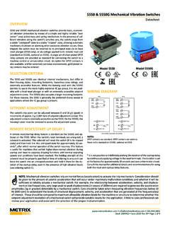
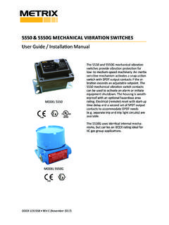
4 Drill out the hole with the correct tap drill size after preparing the sensitive axis of the TRANSMITTER is in line with the mounting stud. The TRANSMITTER can be oriented in any (0 to 360 degree) position. 3. GeneralThe ST5484E is connected like other loop powered transmitters. The following is a summary based on area the field wiring in accordance with the appropriate portion of Figure ST5484E TRANSMITTER requires a minimum of 11 VDC for proper operation. This is the minimum voltage required at the TRANSMITTER (not the power supply), after all other voltage drops across field wiring and receiver input impedance have been accounted for with the maximum 20mA of loop current flowing. The minimum loop power supply voltage required is therefore 11 VDC plus 1 volt for each 50 W of total loop 1: Single- TRANSMITTER loops Multiple- TRANSMITTER loopsCAUTION: Use of a high-speed torque screw-driver may damage the terminal # M9162 REV Y (July 2016) Page 3 of 12 Example:ComponentResistanceSignal wiring10 WDC Input Impedance of receiver250 WTOTAL LOOP RESISTANCE260 WMinimum supply voltage = 260 W (1 V/50 W) + 11 V = VDCThe maximum loop power supply voltage that may be applied is VDC (intrinsically safe) or 30 VDC (explosion proof and non-incendive).
5 The maximum loop resistance (RL) is calcu-lated by the equation: RL = 50 (VS - 11) WExample: RL = 50 (24 - 11) = 650 W for a 24 VDC loop Intrinsically Safe Installation In Hazardous Locations Connect the field wiring in accordance with Metrix drawing 9426 for CSA Class I, (A,B,C & D) and Metrix drawing 9278 for IECEx / ATEX (Ex ia IIC T4 Ga) approvals. The leads must be terminated inside an enclosure with a degree of protection of at least IP20. A Metrix elbow from the 8200 series may be used for these purposes. Refer to Metrix Datasheet 1004457 for additional details on accessories. The ambient temperature range is -40 C to 100 C. The TRANSMITTER requires a minimum of 11 VDC for proper operation. The voltage drop across the specified non-isolated barriers with a 20 mA loop current is VDC. As such, The minimum loop power supply voltage required is VDC plus 1 volt for each 50 W of loop resistance.
6 The maximum loop power supply voltage that may be applied to the safety bar-rier is 26 VDC. Therefore, the maximum loop resistance with a 26 VDC supply is 345 :ComponentResistanceSignal wiring5 WDC Input Impedance of receiver100 WTOTAL LOOP RESISTANCE105 WMinimum supply voltage = 105 (1 V/50 W) + V = Explosion-Proof Installation In Hazardous Locations (CSA) Some models of ST5484E transmitters are CSA certified explosion-proof, CSA US/C, Class I, Div 1, Grps B-D and Class II, Div 1, Grps E-G (explosion proof). Connect the field wiring in ac-cordance with the appropriate portion of Figure 1. Refer to section for loop voltage and resistance requirements. All conduit and junction boxes used must be certified explosion-proof for the class, division, and group required by the application. Installation of the trans-mitter must meet all of the explosion-proof installation requirements of the local governing agency and facility safety Flame-Proof Installation In Hazardous Locations (ATEX, IECEX) Some models of ST5484E transmitters are ATEX/IECEx certified flame-proof, Ex d IIC T4 Gb.
7 Con-nect the field wiring in accordance with the appropriate portion of Figure 1. Refer to section for loop voltage and resistance requirements. All conduit and junction boxes used must be certified flame-proof for the area required by the application. Installation of the TRANSMITTER Doc# M9162 REV Y (July 2016) Page 4 of 12 Doc# M9162 REV Y (July 2016) Page 5 of 12 Doc# M9162 REV Y (July 2016) Page 6 of 12 must meet all of the flame-proof requirements of the local governing agency and facility safety procedures. The Metrix part 8200-001-IEC elbow is required to meet this approval. 4. ELECTROMAGNETIC COMPATIBILITY In order to meet the requirements of electromagnetic compatibility in areas of high electro-magnetic interference, the field wiring must be: Shielded twisted pair cable enclosed in grounded metallic conduit, or Double shielded twisted pair cable with a metallic body cable gland fitting and with the outer shield grounded.
8 Use standard two-conductor, twisted pair, shielded wiring for the long run to the instrumen-tation enclosure. The TRANSMITTER is connected like other loop-powered end devices. 5. CONNECTION TO PLC OR OTHER INDICATING INSTRUMENTThe first step in configuring the PLC, DCS, or other recording instrument is to determine the source of power. The ST5484E requires loop power. Some analog input channels on a PLC or DCS, for example, provide this power from within. If they do not provide power, an external power supply must be provided. Connect the TRANSMITTER field wiring using standard instru-mentation of the display is on the basis of the range of the TRANSMITTER . The measurement parameter name is VIBRATION and the units are in/s (inches per second) or mm/s (mil-limeters per second). The example below is based on a standard in/s VIBRATION level at TRANSMITTER output will (or other) should in/s ( no VIBRATION ) mA ( mA) in/s ( full scale VIBRATION ) mA ( mA) in/secWARNING: ATEX Conditions for Safe Use (Ex d)For temperature classification and safety: Use conduit elbow, Metrix reference 8200-001-IEC, which is a Killark product with reference: Y-3-EX.
9 Ambient Operating Temperature: -40 C to +100 CNOTE: Metrix also strongly recommends the use of our ferrite bead kit (Metrix p/n 100458) as an extra precaution against electromagnetic interference that may be induced in field wiring from subsequently bleeding into the TRANSMITTER . WARNING:ATEX Conditions for Safe Use (Ex ia)The ST5484E is intrinsically safe and can be used in potentially explosive atmo-spheres. This TRANSMITTER must only be associated to intrinsically safe certified appara-tus, and this combination must be compatible as regards intrinsic electrical parameters of certified equipment connected to the TRANSMITTER must meet the following criteria: Uo VDC, Io 100mA; Po Ambient operating temperature -40oC to +100oCDoc# M9162 REV Y (July 2016) Page 7 of 12 Momentary jolts that can occur at start-up, or during some operating condition changes, do not reflect a machine s steady-state operating condition.
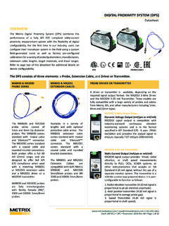
10 To prevent such occurrences from generating nuisance alarms, program a time delay into the alarm such that the indicated VIBRATION level must persist above the alarm setpoint for a preset period of time before an alarm is generated. The indicated VIBRATION level must cross the threshold level and stay above it for a preset time before any alarm action is taken. A 2- to 3-second delay is normally applied to most machinery. Consult Metrix if you have a question about your machine s operating rough starting machinery may also need a start-up time lockout for alarms. A start-up lockout is different than a time delay. A start-up lockout functions the same as a time delay, but is usually set to a much longer time. Both may be TYPICAL TRANSMITTER PLACEMENTThe ST5484E measures SEISMIC VIBRATION ( , VIBRATION velocity) at the attachment point on the machine, using engineering units of in/s (inches per second) or mm/s (millimeters per second) depending on the selected ordering option.