Transcription of StarChips
1 SCT2932 V02_01; Nov/14 Page 1 of 27 LED Driver with LED Driver with LED Driver with LED Driver with IIII nternal nternal nternal nternal SSSS witchwitchwitchwitch Technology S tarC h ip sS tarC h ip sS tarC h ip sS tarC h ip s Product Description SCT2932 is a high efficiency, constant current, continuous mode inductive step-down converter, designed for driving constant current to high power (single or multiple) LED with only 4 external components. SCT2932 operates from input supply between 5V and 33V and provides an externally adjustable output current of up to The SCT2932 is specifically designed with PFM control to enhance the efficiency up to 97%. The Output current can be modify by an external resister, and can adjusted, by applying an external control signal to the DIM pin, The DIM pin will accept a PWM waveform.
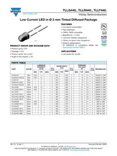
2 Additionally, to ensure the system reliability, SCT2932 is built-in with over temperature protection, and LED open-circuit short-circuit protection to protect system from being damaged. Features output current Wide input voltage range: 5V to 33V High efficiency (up to 97%) Internal NDMOS power switch Single pin on/off and brightness control using PWM Hysteretic PFM improves efficiency at light loads With thermal/soft start /LED open-short detect protection Only 4 external components Up to 1 Mhz switching frequency Typical 3% output current accuracy Applications High power LED lighting Automotive LED lighting Low voltage industrial lighting LED backlighting Constant current source LED Driver with LED Driver with LED Driver with LED Driver with IIII nternal nternal nternal nternal SSSS witchwitchwitchwitch
3 SCT2932 Page 2 of 27 Pin Configuration/Package Type Terminal Description Pin Name I/O Function SW O Drain of NDMOS switch GND - Ground terminal DIM I Dimming control terminal SEN I Connect resistor RS from this pin to VIN to define nominal average output current VIN - Power supply terminal Ordering Information Part Marking Package Unit per reel(pcs) SCT2932C SCT2932C Green TO252-5 80-Tube SCT2932D SCT2932D Green MSOP8 (with thermal pad) 80-Tube SCT2932E SCT2932E Green SOP8 (with thermal pad) 100-Tube SCT2932F 2932F Green SOT89-5 1000 SCT2932J 932J Green SOT23-5 3000 StarChips Technology, Inc. 4F, , Technology Rd., Science-Based Industrial Park, Hsin-Chu, Taiwan, Tel : +886-3-577-5767 , Fax: +886-3-577-6575, E-mail.
4 LED Driver with LED Driver with LED Driver with LED Driver with IIII nternal nternal nternal nternal SSSS witchwitchwitchwitch SCT2932 Page 3 of 27 Application Circuit RsD1L168uH10uF/50 VCledSWVINDIMGNDISENSETTP933C1 GND10uF/50 VTypical applicatiom circuitVIN Block Diagram SCT2932 LED Driver with LED Driver with LED Driver with LED Driver with IIII nternal nternal nternal nternal SSSS witchwitchwitchwitch SCT2932 Page 4 of 27 Maximum Ratings (TA = 25 C) Characteristic Symbol Rating Unit Supply voltage VIN 0-33 (40V for sec) V Output current IOUT A Sustaining voltage at SW pin VSW ~33 (40V for sec) V SOP8TP MSOP8TP TO252 SOT23-6 SOT23-5 Power dissipation1 SOT89-5 PD W SOP8TP MSOP8TP TO252 SOT23-6 SOT23-5 Thermal resistance SOT89-5 RTH(j-a) C/W Operating junction temperature TJ(max) 150 C Operating temperature TOPR -40 to +85 C Storage temperature TSTG -55 to +150 C The absolute maximum ratings are a set of ratings not to be exceeded.
5 Stresses beyond those listed under Maximum Ratings may cause the device breakdown, deterioration even permanent damage. Exposure to the maximum rating conditions for extended periods may affect device reliability. 1. The PCB size is 22mm*20mm (2 layers), power dissipation depends on PCB layout. LED Driver with LED Driver with LED Driver with LED Driver with IIII nternal nternal nternal nternal SSSS witchwitchwitchwitch SCT2932 Page 5 of 27 Electrical Characteristics (VIN=12V, VOUT= , L1=68uH, CIN=COUT=10uF , TA= 25 C; unless otherwise specified.)
6 Characteristic Symbol Conditions Min. Typ. Max. Unit Operating voltage VIN - 5 - 33 V Operating current IIN VIN=5V~33V - 1 2 mA Power down current IOFF VIN=5V~33V - 50 - uA Output current IOUT - - - A Output current Accuracy IOUT/IOUT 150mA IOUT 1A - 3 5 % Efficiency - VIN=12V, IOUT=350mA,Vout= - 97 - % SW Dropout voltage Vsw IOUT=1A - - V Internal propagation delay TPD - 100 200 300 nS VIH - - 5 V Input voltage VIL - 0 - V Sense threshold hysteresis VSENSEHYS - - 15 - % Mean current sense threshold voltage VSENSE - 95 100 105 mV Switch on resistance RDS(ON) VIN=12V, IOUT=350mA, VOUT= - - Minimum switch ON time TONmin - 100 350 450 nS Minimum switch OFF time TOFFmin - 100 350 450 nS Recommended duty cycle range oft switch Dsw - - - maximum operating frequency FreqMAX - 40 - 1000 KHz Thermal Shutdown Threshold TSD - 145 160 175 C Thermal Shutdown Hystersis TSD-HYS - - 20 - C Duty cycle range of PWM signal applied to DIM pin DutyDIM PWM frequency = 1 KHz - 1 - Rise Time of Output current Tr VOUT= , IOUT=350mA, fDIM=1kHz, DutyDIM=50% - 20 - ns Fall Time of Output current Tf VOUT= , IOUT=350mA, fDIM=1kHz.
7 DutyDIM=50% - 20 - ns LED Driver with LED Driver with LED Driver with LED Driver with IIII nternal nternal nternal nternal SSSS witchwitchwitchwitch SCT2932 Page 6 of 27 Device Description (TA=25 C unless otherwise noted) The device, in conjunction with the coil (L1) and current sense resistor (RS), forms a self-oscillating continuous-mode buck converter. Device Operation (Refer to block diagram and Figure 1 - Operating waveforms) Operation can be best understood by assuming that the DIM pin of the device is unconnected and the voltage on this pin (VDIM) appears directly at the (+) input of the comparator.
8 When input voltage VIN is first applied, the initial current in L1 and RS is zero and there is no output from the current sense circuit. Under this condition, the (-) input to the comparator is at ground and its output is high. This turns MN on and switches the SW pin low, causing current to flow from VIN to ground, via RS, L1 and the LED(s). The current rises at a rate determined by VIN and L1 to produce a voltage ramp (VSENSE) across RS. The supply referred voltage VSENSE is forced across internal resistor R1 by the current sense circuit and produces a proportional current in internal resistors R2 and R3. This produces a ground referred rising voltage at the (-) input of the comparator.
9 When this reaches the threshold voltage (Vref), the comparator output switches low and MN turns off. The comparator output also drives another NMOS switch, which bypasses internal resistor R3 to provide a controlled amount of hysteresis. The hysteresis is set by R3 to be nominally 15% of VDIM. When MN is off, the current in L1 continues to flow via D1 and the LED(s) back to VIN. The current decays at a rate determined by the LED(s) and diode forward voltages to produce a falling voltage at the input of the comparator. When this voltage returns to VDIM, the comparator output switches high again. This cycle of events repeat with the comparator input ramping between limits of Vref 15%. LED Driver with LED Driver with LED Driver with LED Driver with IIII nternal nternal nternal nternal SSSS witchwitchwitchwitch SCT2932 Page 7 of 27 Switching Thresholds With VDIM = VREF, the ratios of R1, R2 and R3 define an average VSENSE switching threshold of 100mV (measured on the ISENSE pin with respect to VIN).
10 The average output current IOUTnom is then defined by this voltage and RS according to: IOUTnom = 100mV/RS Nominal ripple current is 15mV/RS LED Driver with LED Driver with LED Driver with LED Driver with IIII nternal nternal nternal nternal SSSS witchwitchwitchwitch SCT2932 Page 8 of 27 Typical Performance Characteristics Efficiency vs. Input Voltage at Various LED Cascaded Number Efficiency vs. input voltage @L=22uH, IOUT=384mA Efficiency vs. input voltage @L=68uH, IOUT=384mA Efficiency vs. input voltage @L=22uH, IOUT=769mA LED Driver with LED Driver with LED Driver with LED Driver with IIII nternal nternal nternal nternal SSSS witchwitchwitchwitch SCT2932 Page 9 of 27 Efficiency vs.