Transcription of STB Self-Checking Optical Touch Buttons Instruction Manual
1 Patent(s) issued or pending Continuous internal Self-Checking operation Diverse-redundant microcontroller-based photoelectric touchbuttons Ergonomically designed to eliminate hand, wrist and armstresses associated with repeated switch operation; require nophysical pressure to operate High excess gain cuts through heavy contamination Immune to ambient light, EMI and RFI interference LED power, output and fault indicators Yellow field cover includedModelCableSupplyVoltageOutput TypeDUO- Touch SGCompatibilitySTBVP64- wire 2 m ( ft) integralcable10 30V dcComplementaryPNPAT-FM-10K, AT-GM/HM-13A, andAT-GM/HM-11KM Two-HandControl Modules, and SC22-3 Safety ControllerSTBVP6Q4-Pin Mini-style QDSTBVP6Q54-Pin Euro-style QDSTBVR815- wire 2 m ( ft) integralcable20 30V ac/dcTwo IndividualComplementaryRelaysSTBVR81Q5-P in Mini-style QDSTBVR81Q65-Pin Euro-style QDStandard 2 m ( ft) cable models are listed. To order the 9 m (30 ft) cable model, add suffix "W/30" to the cabled modelnumber.
2 For example, STBVP6 W/30. Models with a QD connector require a mating :Not a Stand-Alone Safety Device. STB Series Touch Buttons are Self-Checking ergonomic actuatingdevices, but are not, by themselves, safety devices. To be used in a safety application, two STBs mustbe interfaced with a type IIIC two-hand-control module, such as the Banner AT-FM-10K, to meet allrelevant safety requirements of the appropriate standards ( , ISO13851 / EN574).Important - Read This Before ProceedingThe user is responsible for satisfying all local, state, and national laws, rules, codes, and regulations relating tothe use of this product and its application. Banner Engineering Corp. has made every effort to provide completeapplication, installation, operation, and maintenance instructions. Please direct any questions regarding the use orinstallation of this product to the factory applications department at the telephone numbers or address found at user is responsible for making sure that all machine operators, maintenance personnel, electricians, andsupervisors are thoroughly familiar with and understand all instructions regarding the installation, maintenance, and use ofthis product, and with the machinery it controls.
3 The user and any personnel involved with the installation and use of thisproduct must be thoroughly familiar with all applicable standards, some of which are listed within the Engineering Corp. makes no claim regarding a specific recommendation of any organization, the accuracy oreffectiveness of any information provided, or the appropriateness of the provided information for a specific Self-Checking Optical Touch Buttons Original Document64136 Rev. C8 July 201464136 Applicable StandardsANSI B11 Standards for Machine Tools SafetyContact: Safety Director, AMT The Association for Manufacturing Technology, 7901 Westpark Drive, McLean, VA 22102,Tel.: 703-893-2900 ANSI NFPA 79 Electrical Standard for Industrial MachineryContact: National Fire Protection Association, 1 Batterymarch Park, Box 9101, Quincy, MA 02269-9101, Tel.:800-344-3555 ANSI/RIA Safety Requirements for Industrial Robots and Robot SystemsContact: Robotic Industries Association, 900 Victors Way, Box 3724, Ann Arbor, MI 48106, Tel.
4 : 734-994-6088 Applicable International StandardsISO 12100-1 & -2 (EN 292-1 & -2) Safety of Machinery Basic Concepts, General Principles for DesignIEC 60204-1 Electrical Equipment of Machines Part 1: General RequirementsISO 13849-1 (EN 954-1) Safety-Related Parts of Control SystemsISO 13856-1 (EN1760-1), Safety of Machinery Pressure-Sensitive Protective DevicesContact: Global Engineering Documents, 15 Inverness Way East, Englewood, CO 80112-5704, Tel.: 800-854- 7179 OverviewSTB Self-Checking Optical Touch Buttons are Touch -activated photoelectric devices designed to replace capacitive touchswitches and mechanical push Buttons . Their outputs activate while a finger is in the Touch area (yoke) of the switch,interrupting the button s infrared sensing STB Series Buttons are ergonomically designed to eliminate the hand, wrist, and arm stresses associated withmechanical push Buttons . They require absolutely no physical pressure to operate. LED indicators light when power is onand outputs are models are immune to EMI, RFI, and ambient light interference.
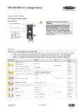
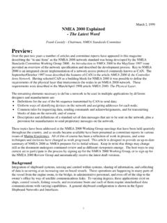
5 STBs have a black polyetherimide upper housing andyellow PBT base. The 30 mm threaded base on all models provides easy mounting and easy retrofitting into existingapplications. Rugged yellow polypropylene (TP) field covers are supplied with all models to prevent inadvertent switchactuation due to objects (such as loose clothing or debris) which might accidentally block the sensing beam. Thepolypropylene material is capable of absorbing high impact (even at low temperatures) and is highly resistant to abrasionand to damage by most CoverBlack PolyetherimideOutputFaultLEDP owerON/OFFLEDS witch" Touch Area"(yoke)Yellow FiberReinforced PBT BaseFigure 1. STB Touch Button featuresWARNING: Point-of-Operation GuardingWhen properly installed, a two-hand controldevice provides protection only for the hands ofthe machine operator. It may be necessary toinstall additional safeguarding, such as safetylight screens, additional two-hand controls, and/orhard guards, to protect all individuals fromhazardous to properly guard hazardousmachinery can result in a dangerouscondition which could lead to serious injuryor Self-Checking Optical Touch Buttons are very similar to the proven and popular OTB Series Buttons .
6 The dual-microcontroller internal design of the new Buttons , however, allows the hookup to a Banner DUO- Touch SG Two-Hand-Control Safety Module, or other two-hand-control designed to meet Type IIIC requirements per ISO 13851 (EN 574)(requiring 1 normally open and 1 normally closed contact per input channel). These microcontrollers perform a continuous STB Self-Checking Optical Touch - Tel: +1-763-544-3164P/N 64136 Rev. Cself-check. The emitter is continuously pulsed, and receiver response is checked accordingly by the microcontrollers. STBS eries Touch Buttons are designed to immediately detect any internal component failure, go into a lockout mode, andindicate the failure with a flashing green Fault STB outputs are not monitored by the STB circuitry, and have no external device monitoring feedback. Outputmonitoring must be accomplished by using an external device, such as a Type IIIC Two-Hand-Control Series Touch Button LED IndicatorsPower On (green):Solid when power is appliedOutput, Fault (green):Solid when button is activatedOff when button is not activatedFlashing when a fault condition is detectedSTB Series Self-Checking Touch Buttons were designed primarily to provide the Self-Checking function required in control-reliable machine cycle initiation applications.
7 STBs also are suitable for use anywhere mechanical push Buttons or theoriginal OTB Touch Buttons are the solid-state and relay-output versions have complementary outputs and can be connected to switch power toequipment as long as the STB s switching voltage and current limits are not must be connected to a type IIIC Two-Hand-Control circuit module, in most cases, when used to initiate potentiallydangerous machine and ANSI require that the hand controls be mounted to protect them from accidental or unintentional operation. Useshields, covers, rings, collars, dividers, or similar protection to prevent accidental switch actuation and to discourage use offorearms or elbows. European standard ISO 13851 (EN 574) includes a detailed discussion of approaches to protection ofhand controls. The hand controls must be arranged far enough apart so that the operator cannot operate both handcontrols by the use of one arm. Typically, this distance is not less than 550 mm ( ") in a straight line, but using guardsor alternate mounting arrangement can allow shorter distances, per ISO 13851 (EN574).
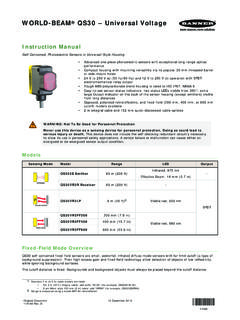
8 This standard also recommendsthat hand controls be arranged on a horizontal (or nearly horizontal) surface that is 1,100 mm ( ") above the ergonomic principles to avoid unnecessary fatigue in the installation of the hand controls. Install the touchbuttons at a height and in a location that will be comfortable for the ISO 13851 (EN574) Two-Hand Control, Ergonomic Guidelines, and EN894 Safety of Machinery Ergonomic Requirements Control Actuators forfurther following figure shows two methods for mounting the Touch Buttons , to prevent accidental switch actuation. Whenmounting them on top of the control bar, the protective field covers should be in place, as shown; or for added protection,mount the Touch Buttons sideways under and/or behind a protective hood, rather than on top of the bar, removing thefield covers. This side mount prevents an object from being left in the path of the beam, intentionally bypassing thesafeguard. In addition, shields, covers, rings, collars, dividers, or similar protection may be used to prevent accidentalswitch actuation.
9 Figure 2. Protect STB Touch Buttons to prevent defeat or inadvertent actuationSTB Self-Checking Optical Touch Buttons P/N 64136 Rev. - Tel: +1-763-544-31643 CAUTION: Install Hand Controls to Prevent Accidental ActuationTotal protection for the two-hand control system from defeat is not possible. However, the user isrequired by and International standards to arrange and protect hand controls tominimize the possibility of defeat or accidental : Hand ControlsThe environment in which hand controls are installed must not adversely affect the means ofactuation. Severe contamination or other environmental influences may cause slow response or falseOn conditions of mechanical or ergonomic Buttons . This may result in exposure to a Control Safety Distance (Minimum Distance)Both hand controls must be located far enough away from the nearest hazard point that the operator cannot reach thehazard with a hand or other body part before the hazardous motion ceases. This is the separation distance ( safetydistance ), and may be calculated as : Location of Touch Button ControlsHand controls must be mounted a safe distance from moving machine parts, as determinedby the appropriate standard.
10 It must not be possible for the operator or other non-qualified personsto relocate them. Failure to establish and maintain the required safety distance may result inserious injury or ApplicationsThe Safety Distance formula, as provided in ANSI :Part-Revolution Clutch Machinery (the machine and its controls allow the machine to stop motion during the hazardous portion of the machinecycle)Ds = K x (Ts + Tr + Th)For Full-Revolution Clutch Machinery (the machine and its controls are designed to complete a full machine cycle)Ds = K x (Tm + Tr + Th)Dsthe Safety Distance (in inches)Kthe OSHA/ANSI recommended hand-speed constant (in inches per second), in most cases is calculated at 63 in/sec, but may vary between 63to 100 in/sec based on the application circumstancesnot a conclusive determination; consider all factors, including the physical ability of the operator, when determining the value of K to be usedThthe response time of the slowest hand control from the time when a hand disengages that control until the switch opensTh is usually insignificant for purely mechanical switches.