Transcription of Steam Turbines and Boilers - UNIRI
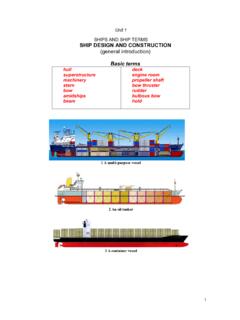
1 24 Under construction Learning resources based on authentic materials Steam Turbines and Boilers Steam Turbines for Marine Propulsion Video: Marine Steam turbine engines have largely been replaced by the more economical marine two stroke diesel engine, mainly for commercial reasons as the diesel engine is much more economical. Notwithstanding this there are still a few about, running like clockwork- their one big selling point along with reliability, little maintenance, and high speed- pushing large cruisers and battleships along at forty knots, but they are very thirsty.
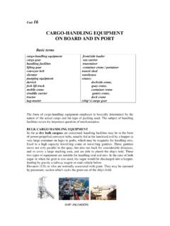
2 Let's find out how Steam Turbines work in the context of marine turbine engines. The Cross Compound Double Reduction turbine For marine applications, the cross compound double reduction Steam turbine was a popular choice because it was more compact, taking up less space in the ships engine-room. It also had the advantage of a built-in astern turbine giving easier astern movement, with up to 50% astern output power as that of the ahead turbine . This was a big advantage when the first oil super tankers were built they took half a mile to stop from full ahead!
3 In operation, the Steam is supplied from the ship's boiler as high pressure, high temperature superheated Steam and passes into the high pressure turbine , (HP) expanding through the blades and exiting into the low pressure turbine through a large bore insulated pipe. From here the low pressure Steam passes through LP turbine blades, exiting from these and then being drawn by vacuum from the last few stages into main condenser. The high pressure and low pressure Turbines are really separate Turbines having their own drive shafts, which are coupled to a double reduction gearbox that decreases their revolutions from several thousand to about 100 RPM, the normal operating propeller shaft speed.
4 The high pressure turbine rotor also has several rows of blades that are used as an astern turbine , which enables the ship to maneuver when arriving or departing ports. Also the astern turbine can be used in an emergency to avoid collision at sea, and although I have had to emergency stop and put astern a large marine main diesel engine, I have thankfully never had to carry this operation out on any steamships that I served on as marine engineer, as they were all tankers, so I cannot comment on its viability. Both the high pressure and low pressure Steam Turbines have glands at each end which stop the Steam from escaping into the engine-room from the high pressure stage and which stop the loss of condenser vacuum through the low pressure stage.
5 These glands are known as labyrinth type and, as the name suggests, are made up of a series of three rings and are supplied with two different pressures, which effectively seals both Turbines shafts and end covers, with the supplied Steam exiting to the gland cooler. A common lube oil system is used to lubricate the various components and keep them cool by pumping the oil through a cooler. The oil is drawn from the drain tank a through a set of magnetic strainers by the lube oil pump into a set of duplex filters, then onto the main lube oil cooler before supplying oil under pressure to the turbine white metal bearings, gearbox, gearbox sprays, and thrust block.
6 There is also a secondary back-up lube oil pump driven by the turbine shaft supplying oil to gearbox and thrust. An overhead tank, usually positioned at the top of the engine-room, is also supplied by the pump through a bleed off orifice. From the tank there is a vertical overflow pipe incorporating a circular glass window, usually illuminated from behind, from which the oil can be observed flowing back down into the system. The reason for the header tank is in the event of a black-out or loss of a lube-oil pump, the header tank has the capacity to keep the turbine bearings supplied with oil until the turbine stops rotating, with the auxiliaries being supplied by the secondary pump.
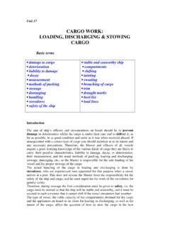
7 It is usual to have a lube oil purifier or centrifuge located within the system to remove any ingress of water or impurities from the oil. There is also another lube oil system known as gravity feed whereby the lubrication of all the components is by the overhead tank; this system is shown in the sketch. Warming Through After the Turbines and Steam supply/exhaust have being idle in port, about two hours before standby, the turning gear should be withdrawn and the Steam supply and exhaust system slowly warmed through. This is carried out firstly by raising a full vacuum about 28-29 Hg, and once this has been achieved, the ahead Steam valve should be slowly opened a few notches rotating the shaft a few revs only, holding for one minute before shutting again, the astern turbine also being operated similarly.
8 This should be continued to ensure all the pipe-work, turbine covers and rotors, expansion plates and condensate returns to Boilers are all well warmed through and expanded up to working temperature. Remember any water in the system will damage the Turbines so only superheated Steam should be used, and operate the Steam drains and check the Steam traps if applicable A typical Steam turbine layout in a ship's engine room is shown below. Steam Turbines and gearing - operating principle The Steam turbine has until recently been the first choice for very large power marine propulsion units.
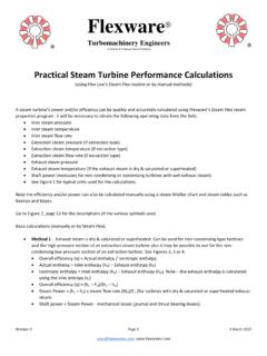
9 Its advantages of little or no vibration, low weight, minimal space requirements and low maintenance costs are considerable. Furthermore a turbine can be provided for any power rating likely to be required for marine propulsion. However, the higher specific fuel consumption when compared with a diesel engine offsets these advantages, although refinements such as reheat have narrowed the gap. Fig: Energy conversion in a Steam turbine The Steam turbine is a device for obtaining mechanical work from the energy stored in Steam . Steam enters the turbine with a high energy content and leaves after giving up most of it.
10 The high-pressure Steam from the boiler is expanded in nozzles to create a high-velocity jet of Steam . The nozzle acts to convert heat energy in the Steam into kinetic energy. This jet is directed into blades mounted on the periphery of a wheel or disc (Figure above). The Steam does not 'blow the wheel around'. The shaping of the blades causes a change in direction and hence velocity of the Steam jet. Now a change in velocity for a given mass flow of Steam will produce a force which acts to turn the turbine wheel, mass flow of Steam (kg/s) x change in velocity (m/s) = force (kgm/s2).