Transcription of Stresses in PressureVessels - Elsevier
1 1 Stresses in PressureVesselsDESIGN PHILOSOPHYIn general, pressure vessels designed in accordance withthe ASME Code, Section VIII, Division 1, are designed byrules and do not require a detailed evaluation of all is recognized that high localized and secondary bendingstresses may exist but are allowed for by use of a highersafety factor and design rules for details. It is required, how-ever, that all loadings (the forces applied to a vessel or itsstructural attachments) must be considered. (See Reference 1,Para. UG-22.)While the Code gives formulas for thickness and stress ofbasic components, it is up to the designer to select appro-priate analytical procedures for determining stress due toother loadings. The designer must also select the most prob-able combination of simultaneous loads for an economicaland safe Code establishes allowable Stresses by stating in (c) that the maximum general primary membranestress must be less than allowable Stresses outlined in materialsections.
2 Further, it states that the maximum primary mem-brane stressplusprimary bending stress may not exceed the allowable stress of the material sections. In othersections, specifically Paras. 1-5(e) and 2-8, higher allowablestresses are permitted if appropriate analysis is made. Thesehigher allowable Stresses clearly indicate that different stresslevels for different stress categories are is general practice when doing more detailed stressanalysis to apply higher allowable Stresses . In effect, thedetailed evaluation of Stresses permits substituting knowl-edge of localized Stresses and the use of higher allowablesin place of the larger factor of safety used by the Code. Thishigher safety factor really reflected lack of knowledge aboutactual calculated value of stress means little until it is associ-ated with its location and distribution in the vessel and withthe type of loading that produced it.
3 Different types of stresshave different degrees of designer must familiarize himself with the varioustypes of stress and loadings in order to accurately applythe results of analysis. The designer must also considersome adequate stress or failure theory in order to combinestresses and set allowable stress limits. It is against this fail-ure mode that he must compare and interpret stress values,and define how the Stresses in a component react and con-tribute to the strength of that following sections will provide the fundamentalknowledge for applying the results of analysis. The topicscovered in Chapter 1 form the basis by which the rest ofthe book is to be used. A section on special problems andconsiderations is included to alert the designer to more com-plex problems that ANALYSISS tress analysis is the determination of the relationshipbetween external forces applied to a vessel and the corre-sponding stress.
4 The emphasis of this book is not how to dostress analysis in particular, but rather how to analyze vesselsand their component parts in an effort to arrive at aneconomical and safe design the difference being that weanalyze Stresses where necessary to determine thickness ofmaterial and sizes of members. We are not so concernedwith building mathematical models as with providing astep-by-step approach to the design of ASME Code is not necessary to find every stress but rather to know thegoverning Stresses and how they relate to the vessel or itsrespective parts, attachments, and starting place for stress analysis is to determine allthe design conditions for a given problem and then deter-mine all the related external forces. We must then relatethese external forces to the vessel parts which must resistthem to find the corresponding Stresses .
5 By isolating thecauses (loadings), the effects (stress) can be more designer must also be keenly aware of the types ofloads and how they relate to the vessel as a whole. Are the1effects long or short term? Do they apply to a localizedportion of the vessel or are they uniform throughout?How these Stresses are interpreted and combined, whatsignificance they have to the overall safety of the vessel , andwhat allowable Stresses are applied will be determined bythree things:1. The strength/failure theory The types and categories of The hazard the stress represents to the Stress AnalysisPressure vessels commonly have the form of spheres,cylinders, cones, ellipsoids, tori, or composites of the thickness is small in comparison with other dimen-sions (Rm/t > 10), vessels are referred to as membranes andthe associated Stresses resulting from the contained pressureare called membrane Stresses .
6 These membrane Stresses areaverage tension or compression Stresses . They are assumedto be uniform across the vessel wall and act tangentially to itssurface. The membrane or wall is assumed to offer no resis-tance to bending. When the wall offers resistance to bend-ing, bending Stresses occur in addition to membrane a vessel of complicated shape subjected to internalpressure, the simple membrane-stress concepts do not suf-fice to give an adequate idea of the true stress situation. Thetypes of heads closing the vessel , effects of supports, varia-tions in thickness and cross section, nozzles, external at-tachments, and overall bending due to weight, wind, andseismic activity all cause varying stress distributions in thevessel. Deviations from a true membrane shape set up bend-ing in the vessel wall and cause the direct loading to varyfrom point to point.
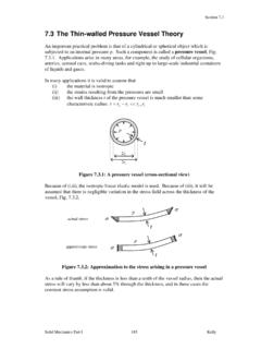
7 The direct loading is diverted from themore flexible to the more rigid portions of the vessel . Thiseffect is called stress redistribution. In any pressure vessel subjected to internal or externalpressure, Stresses are set up in the shell wall. The state ofstress is triaxial and the three principal Stresses are: x longitudinal/meridional stress circumferential/latitudinal stress r radial stressIn addition, there may be bending and shear Stresses . Theradial stress is a direct stress, which is a result of the pressureacting directly on the wall, and causes a compressive stressequal to the pressure . In thin - walled vessels this stress is sosmall compared to the other principal Stresses that it isgenerally ignored. Thus we assume for purposes of analysisthat the state of stress is biaxial. This greatly simplifies themethod of combining Stresses in comparison to triaxial stressstates.
8 For thickwalled vessels (Rm/t < 10), the radial stresscannot be ignored and formulas are quite different fromthose used in finding membrane Stresses in thin ASME Code, Section VIII, Division 1, is basically fordesign by rules, a higher factor of safety is used to allow forthe unknown Stresses in the vessel . This higher safetyfactor, which allows for these unknown Stresses , can imposea penalty on design but requires much less analysis. Thedesign techniques outlined in this text are a compro-mise between finding all Stresses and utilizing minimumcode formulas. This additional knowledge of Stresses warrantsthe use of higher allowable Stresses in some cases, while meet-ing the requirements that all loadings be conclusion, membrane stress analysis is not completelyaccurate but allows certain simplifying assumptions to bemade while maintaining a fair degree of accuracy.
9 The mainsimplifying assumptions are that the stress is biaxial and thatthe Stresses are uniform across the shell wall. For thin -walledvessels these assumptions have proven themselves to bereliable. No vessel meets the criteria of being a truemembrane, but we can use this tool with a reasonabledegree of THEORIESAs stated previously, Stresses are meaningless until com-pared to some stress/failure theory. The significance of agiven stress must be related to its location in the vesseland its bearing on the ultimate failure of that , various theories have been derived to com-bine and measure Stresses against the potential failuremode. A number of stress theories, also called yield cri-teria, are available for describing the effects of combinedstresses. For purposes of this book, as these failure theoriesapply to pressure vessels, only two theories will be are the maximum stress theory and the maximumshear stress theory.
10 Maximum Stress TheoryThis theory is the oldest, most widely used and simplest toapply. Both ASME Code, Section VIII, Division 1, andSection I use the maximum stress theory as a basis fordesign. This theory simply asserts that the breakdown of2 pressure vessel Design Manualmaterial depends only on the numerical magnitude of themaximum principal or normal stress. Stresses in the otherdirections are disregarded. Only the maximum principalstress must be determined to apply this criterion. Thistheory is used for biaxial states of stress assumed in a thin - walled pressure vessel . As will be shown later it is unconser-vative in some instances and requires a higher safety factorfor its use. While the maximum stress theory does accuratelypredict failure in brittle materials, it is not always accuratefor ductile materials. Ductile materials often fail along lines45 to the applied force by shearing, long before the tensileor compressive Stresses are theory can be illustrated graphically for the fourstates of biaxial stress shown in Figure can be seen that uniaxial tension or compression lies onthe two axes.