Transcription of Structural Engineering and Materials
1 VIRGINIA POLYTECHNIC INSTITUTE. AND STATE UNIVERSITY. The Charles E. Via, Jr. Department of Civil and Environmental Engineering Blacksburg, VA 24061. Structural Engineering and Materials VEHICULAR ACCESS DOORS UNDER HURRICANE FORCE WIND. PRESSURE: ANALYSIS METHODS AND A DESIGN TOOL. by Tian Gao Graduate Research Assistant Cristopher D. Moen, , Principal Investigator Submitted to the: metal building manufacturers association 1300 Sumner Ave Cleveland, OH 44115-2851. Report No. CE/VPI-ST-11/02. August 2011. ACKNOWLEDGEMENTS The authors are appreciative of the support they received from MBMA throughout this project, especially the thoughtful advice from the steering group. Mr. Jerry Hatch of NCI provided valuable guidance throughout the test program. Coordination with the sponsor was provided by Dr. Lee Shoemaker and Mr. Dan Walker of MBMA. Mr. Joe Hetzel of DASMA provided important input regarding access door design procedures and details.
2 Dr. Ray Plaut, professor emeritus in the Civil and Environmental Engineering Department at Virginia Tech, assisted in the derivation of the elastica beam equations used to predict access door behavior. TABLE OF CONTENTS Acknowledgements 1. Introduction 3. Research Motivation 3. Access Door Anatomy 3. Access Door Experiments 5. Research Strategy 6. Analytical Framework 7. Formulation 7. Governing Equations 9. Initial Conditions 10. Solution 11. Flexible Jamb Stiffness Prediction 12. Typical Jamb Details 12. Prediction Method 12. Section web Bending 14. Jamb Twist 15. Example Douglasville Experiments 18. Beam Strip Model Validation 22. FE Meshing 22. Boundary Conditions 22. Loading 24. Solution Algorithm 25. Comparison of FE Model to Experiments 25. Comparison of FE Model to Beam Strip Model 26. Comparison to DASMA Prediction 29. Prediction Method Implementation 30. Conclusions and Future Work 31. References 32.
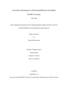
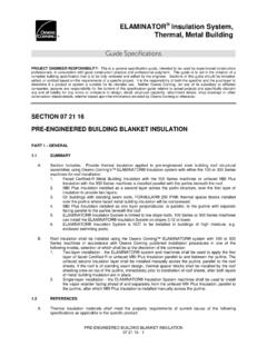
3 Appendix A - DASMA Prediction Method 33. Appendix B DBCI Series 5000 Door Details 37. Appendix C- DASMA Method 39. Appendix D - Matlab Code 41. Appendix E - Shell Element Comparisons 44. Element types 44. Curtain Shell Element 44. Behavior of ABAQUS Shell Elements 45. Appendix F Navier-stokes exact plate solution 50. 2. INTRODUCTION RESEARCH MOTIVATION It is essential that rolling sheet metal access doors in metal buildings, and the door jambs they are attached to, resist high pressures during an extreme wind event. Catastrophic damage to the building and its contents can occur if the door fails, as documented by recent post- hurricane surveys conducted after Hurricanes Ike and Katrina (FEMA 2005a; FEMA 2005b; RICOWI. 2006; RICOWI 2007; RICOWI 2009). Once the door is breached, pressure accumulates inside the building that can fail the walls and roof (Figure 1). Estimated yearly damage from wind- induced damage in the is billion dollars (NOAA 2011), reinforcing the need for reliable wind resistance structures and accurate wind design procedures.
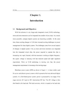
4 Figure 1. metal building roof failures caused by internal wind pressure (RICOWI 2009). ACCESS DOOR ANATOMY The most common access door failure mode during a high wind pressure event is disengagement of the door from the track attached to the jamb as shown in Figure 2a (FEMA. 2005). To avoid track disengagement in hurricane-prone regions, steel J-hooks called wind- locks (Figure 2b), are riveted to the door curtain and placed in tracks attached to the door jambs. The wind-locks float freely within the tracks during service, allowing the door to roll up and down. During an extreme wind event the curtain deflects out of plane, and the wind-locks engage a wind-bar attached to the door jambs (Figure 3, Section A-A). This engagement limits out-of-plane door deflection through the development of catenary forces that can overload the door jamb if not designed properly (Figure 2c). The Door and Access Systems manufacturers association (DASMA) provides a method to predict wind-lock demand forces on door jambs, see Appendix A.
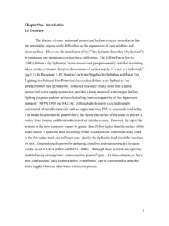
5 This procedure calculates the wind pressure required to deflect the door enough to close the gap between the wind-lock and 3. wind-bar. Once the wind-locks have engaged, the geometry of the door is assumed fixed, , there is no additional out-of-plane curtain deformation. Wind-lock reactions are calculated based on this fixed geometry with catenary equations and an evenly distributed pressure on the door. (a) (b) (c). Figure 2. (a) Access door failure by disengagement of the door from the jamb track, (b) wind-locks, (c) jamb failure of an access door with wind-locks Figure 3. Typical access door details 4. ACCESS DOOR EXPERIMENTS An experimental evaluation of the DASMA prediction equations for wind-lock force and door deflection was performed in 2009 (Gao and Moen 2009; Gao and Moen 2010). A 10 ft by 10 ft access door with wind locks was tested in both negative pressure (pulling door out of the building ) and positive pressure (pushing the door into the building ) with a custom vacuum chamber at DBCI in Douglasville, GA, see Figure 4a.
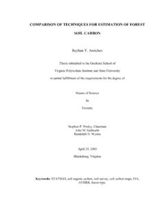
6 The door had 18 wind locks along each vertical edge of the door, and the door jambs were cold-formed steel C-sections braced by Z- section girts (Figure 5). DBCI shop drawings for this door are provided in Appendix B. (a) (b). Figure 4. (a) Rolling sheet metal door experiment, (b) Deformed jamb after test (Gao and Moen 2009). Type: B. Type: D. Type: A Z 14. Type: B Z 12. Type: A Type: A Type: C C 13. Type: C. Type: D 10'6 . 15'8 . Type: A Type: A. Type: C. Type: C. 12'8 7'4 . Type: A Type: A. 10'. Type: A Type: A 5'2 . 3'6 . 5' 10' 5'. 24'. Figure 5. Cold-formed steel door framing (Gao and Moen 2009). 5. Each wind lock was instrumented with strain gauges, and strains were recorded as pressure was applied to the door. Maximum measured forces in the wind-locks were approximately 50%. lower than that predicted by the DASMA procedure, compare 380 lbs per wind-lock in the experiments (Gao and Moen 2009) to 760 lbs per wind-lock predicted by DASMA at a pressure of 60 psf (see Appendix C).
7 Measured out-of-plane door deflections were more than double that of the DASMA predictions, compare 12 in. (Gao and Moen 2009) to in. predicted by DASMA (see Appendix C) at 60 psf. The difference between the measured and predicted behavior was attributed to deflection of the cold-formed steel C-section jambs (Figure 4b), which accommodated additional in-plane movement of the door after the wind locks engaged. A small in-plane movement results in a large out-of-plane deformation, approximately in. to 6 in. for the door studied in Douglasville. Therefore, as the C-section jamb deflected from the applied wind-lock forces, curtain deflection was amplified. The additional door deflection accommodated a funicular shape that reduced the in-plane component of the catenary force transferred to the door jamb. It was concluded from this experimental program that wind lock forces and door deflection are sensitive to jamb stiffness, and this stiffness should be included in a design approach for vehicular access doors.
8 The DASMA design procedure was determined to be viable when the door jambs are rigid, however it underestimates door deflections and overestimates catenary forces for access doors with flexible door jambs. RESEARCH STRATEGY This research program aims to complement the existing DASMA access door wind analysis approach with a general procedure applicable to a wider range of access doors and jamb details, including doors attached to flexible jambs, , cold-formed steel framing. The generalized analysis procedures are founded on an analytical framework of nonlinear Euler-Bernoulli elastica differential equations. Jamb stiffness boundary conditions are approximated with hand calculations employing existing cantilever and torsional stiffness Engineering expressions. The analytical framework is validated with thin-shell finite element modeling and the Douglasville experimental data, and then implemented as a custom built, freely available Matlab program.
9 The elastica analytical framework is introduced in the following section. 6. ANALYTICAL FRAMEWORK FORMULATION The access door experiments in Douglasville, GA (Gao and Moen 2009) demonstrated that away from the top and bottom of the door, curtain deflections due to wind pressure resulted in primarily one-way deformation across the span of the door. If one-way action is assumed, the prediction of catenary forces and deflections in a vehicular access door can be simplified to an inextensible beam strip model like that shown in Figure 6. This assumption is consistent with the existing DASMA prediction approach, except translational springs have been added to the beam ends to simulate door jamb flexibility. Figure 6. Curtain strip model notation Beam strip behavior can be represented with the elastica solution for beams, which employs Euler-Bernoulli beam theory and accommodates large flexural deformations (Timoskenko and Gere 1961).
10 Shear deformations are neglected. Defining X and Y as the door's deflected shape in Cartesian coordinates, t as the curvilinear distance along the curtain, and the slope of the door curtain as (t), the change in X and Y at location t is X(t)' = cos(! (t)) (1). 7. Y(t)' = sin(! (t)) , (2). where t is a relative indicator of position over the half span ranging from 0 to 1. Summing the changes in X and Y by integrating Eqs. (1) and (2) results in expressions for the deflected shape as a function of t t X(t) = ! cos(! (t))dt (3). 0. t Y (t) = ! sin(! (t))dt . (4). 0. Euler-Bernoulli beam theory dictates that the beam moment M(t) is proportional to curvature d (t)/dt and flexural rigidity EI as given by M (t). ! (t)'= (5). EI . For a vehicular access door, the moment of inertia, I, would be calculated with the height of door attributed to one wind-lock, , a tributary width as shown in Figure 7. Figure 73. Windlock tributary distance Ws is in.