Transcription of SUBJECT: PUMP TYPES & OPERATIONS ABOUT …
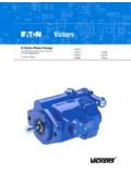
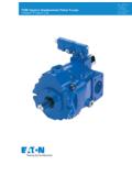
1 subject : PUMP TYPES & OPERATIONSABOUT THE SESSIONThis session will highlight different TYPES of pumps and its working. INTRODUCTIONIn Hydraulic system, the pump converts mechanical energy (hydraulic horsepower) by pushing fluid into the system. All pumps work on the same principle generating an increasing volume on the intake side and a decreasing volume on the discharge side; but the different TYPES of pumps very greatly in methods and sophistication. TABLE OF CONTENTSTYPES OF Positive Displacement Displacement Gear Gear Pump Fixed Pump Variable Axis Piston OBJECTIVES:To understand in depth, the working of the following sophisticated pumps used in latest power hydraulic systems. Gear PumpsVane PumpsPiston PumpsPUMP RATINGSA pump is generally rated by its maximum operating pressure capability and output flow at a given drive speed. The pressure rating of a pump is determined by the manufacturer and is based upon reasonable service-life expectancy under specified operating conditions.
2 Flow capacity of a pump can be expressed as displacement per OF PUMPST here are two basic TYPES of pumps . Non-Positive Displacement Pump Positive Displacement Pump1. Non-Positive Displacement Pump - Centrifugal PumpThis pump design is used mainly for fluid transfer in systems where the only resistance found is created by the weight of the fluid itself and friction. Most non-positive displacement pumps . (Figure 17-2) operate by centrifugal force. Fluids entering the center of the pump housing are thrown to the outside by means of a rapidly driven impeller. There is no positive seal between the inlet and outlet ports, and pressure capabilities a function of drive it provides a smooth, continuous flow, the output from this type of pump is reduced as resistance is increased. In fact, it is possible to completely block off the outlet while the pump is running. For this and other reasons, non-positive displacement pumps are seldom used in power hydraulic systems today.
3 These properties make it a more likely choice for a water pump in a car engine, dishwasher or washing machine. It could also be used as a supercharge pump for a positive displacement . Positive Displacement Pump The positive displacement pump is most commonly used in industrial hydraulic systems. A positive displacement pump delivers to the system, a specific amount of fluid per stroke, revolution, or cycle. This type of pump is classified as fixed or variable displacement pumps have a displacement which cannot be changed without replacing certain components. With some, however, it is possible to vary the size of the pumping chamber (and the displacement) by using external controls. These pumps are known as variable displacement vane pumps and piston units can be varied from maximum to zero delivery. Some are capable of reversing their flow as the control crosses a center or neutral position. The pressure is determined by the workload, and except for leakage losses, the output is independent of outlet pressure.
4 This makes the positive displacement pump more appropriate for use in the transmission of three best-known positive displacement pumps : gear pumps , vane pumps , and piston GEAR PUMP WITH INTERNAL GEARINGIt comprises mainly a housing (1), in which a pair of gears run with such low axial and radial play, that the unit is practically suction side (blue) is connected to the tank. The pressure side (red) is connected to the hydraulic inner gear 2 is driven in the direction of the arrow, and takes external gear 3 along with it in the same rotary movement causes the gears to separate, so that the gear spaces are negative pressure caused by this and the atmospheric pressure on the fluid level in the tank cause fluid to run from the tank to the pump. One generally says the pump sucks .The fluid fills the gear spaces, which form closed chambers with the housing and the crescent 4, during further movement, and is pushed to the pressure side (red).The gears then interlock once more and push the fluid from the gear GEAR PUMP WITH EXTERNAL GEARINGThe gears which would come into contact with one another prevent return flow from the pressure chamber to the suction this case, 2 external gears would come into contact with one another.
5 Gear 2 is driven in the direction of the arrow, and causes gear 3 to move with it in the opposite direction. The suction process is identical to that previously described for the internally geared fluid in gear chambers 4 is pushed round the outside and out of the gear spaces on the pressure side (red).It can easily be seen from the sectional drawing that the gears close the spaces before these are completely unloading in the remaining chambers, very high pressure would occur, which would result in hard pulsating running of the this reason, unloading bores are arranged at this position on the side of the bearing blocks. The so called compressed fluid is thus fed into the pressure further point worthy of note is the side tolerance play between gears 5 and bearing blocks 6. fig. 4It tolerance play too great low friction high leakageIf tolerance play too low high friction high leakageIf the tolerance play is designed as a fixed aperature, leakage increases along with wear.
6 The volumetric loss also increases with increasing operating pump design incorporates a hydrostatic bearing balance. The bearing blocks are pushed on to the gears by cams 7, which are affected by system play therefore adjusts itself according to the system pressure. This results in a high degree of efficiency, independent of speed and technical detailsdisplacement 100 pressureup to 250 VANE pumps WITH FIXED DISPLACEMENT Single PumpCam 1 has an internal running surface on double eccentric design. The rotor is in drive part. On its circumference, two vanes 3 (double vanes, which can be pushed against each other are fitted in radially arranged the rotor is turned, the centrifugal force and the system pressure being one against each and radially moveable vanes towards the outside. They lie with their external edge to the inner running area of the cells (transporting chambers are formed by 2 pairs of vanes, the rotor one cam and control discuss arranged on the (suction side, blue and system pressure side red) of the fluid take place by means of the control discs (not shown)To make things easier to understand external supply and drain are shown in the drawing ( ).))
7 For flow delivery, the rotor is moved in one direction of the arrow. Near the suction line above and below), the vanes 4 are still too small if the rotor is turned further, the vanes increase and fill up with oil. When these cells have reached their maximum size (largest distance from the internal running space to the center point of the motor, they are separated from the suction side by means of control discs. They are then connected to the pressure side. The vanes are pushed into groves by the form of the cam curve. The vane volume decrease once more. The fluid is thus pushed to the pressure the cam curve is designed as double eccentric, each vane is involved in the delivery process twice per the same time, two suction chamber and two pressure chambers lie opposite each other, whereby the drive shaft is hydraulic pressure is applied to the back of vanes sealing is thus achieved in addition to the double seal , a friction may not be too great, both vanes in a motor grove have chamfers opposite each other ( )The chamfers on the vanes cause a pressure balance between running and return side.
8 The rolling surface of vanes remains as contact surface for the pressure. Higher contact pressure is not necessary on such suction side. The backs of the vanes are thus unloaded to tank. DOUBLE PUMP ASSEMBLIESD ouble pumps (figures ) provide a single power source capable of serving two separate hydraulic circuits or providing greater volume through combined delivery. Most double pumps have a co on inlet in a center housing. The outlet for one unit, usually the larger of the two is the shaft end body. The second outlet is in the cover. Some TYPES of double pumps have separate inlets, although they can be mounted in multiples. Both kinds need only one drive motor, however, double pumps that have separate inlets require separate piping. Cartridge construction for double pumps is essentially the same as in single unit, making numerous combinations of sizes and displacements VANE pumps WITH VARIABLE DISPLACEMENT AND PRESSURE CONTROLWith this type of pump, the displacement volume can be adjusted as the set maximum operating delivery process follows the principle as described for fixed displacement pump this case, however, the cam is a circular concentric.
9 A spring 2 pushes the cam into its eccentric outlet position towards the motor. The maximum eccentric and thus the maximum displacement volume can be set by means of the screw 5. The spring force can also be adjusted by means of is tangential adjustments of the cam by means of height adjustment screw pressure which builds up due to working resistance ) at the user, cylinder with load) affects the internal running surface of the cam on the pressure side. this results in a horizontal force component which operates towards the spring ( )If the pressure force exceeds the set spring force (equivalent to certain pressure), the cam ring moves from eccentric towards zero position. The eccentric decreases. The delivery flow adjusts itself to the level required by the user. If no fluid is taken by the user and the set pressure is thus reached, the pump regulates flow to almost zero, operating pressure is maintained and only the leakage oil replaced, Because of this, loss of power and heating of the fluid is kept to a the initial spring tension is achieved, the cam ring moves.
10 Flow decreases are gradient of the performance curve depends on the spring characteristics whereby the gradient with a certain spring and different pressure improve the sensitivity of response, the pump can be fitted with 4 different springs corresponding to 4 pressure also show the bleed valve 7 fitted as standard commissioning is made easier by automatic valve poppet is pushed back by spring the valve open. The valve remains open as long as air escapes during start up. If fluid flow through the valve, the poppet is pushed against the spring and the connection closed technical datadisplacement volume upto 47cc rev. (4 sizes)operating pressure upto 100 bar. PISTON pumps All piston pumps operate on the principle that a piston reciprocating in a bore will draw fluid in as it is retracted and expel it as it moves forward. The two basic designs are radial and axial, both available as fixed or variable-displacement models.