Transcription of Locating Principles & Devices
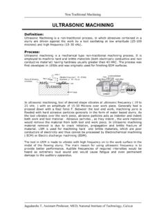
1 Locating Principles & Devices1 Locating PRINCIPLESTo position the work piece to tool, to ensure precision in machining Locating : dimensional and positional relation- ship b/w work piece and toolLocator: device to establish and maintain position of a part in a jig or fixture2 BASIC PRINCIPLESP ositioning the locatorAccuracy & tolerancesFool proofingDuplicate locationMotion economy31- Positioning the locatorsLocators should contact the work (preferably machines surface) on a solid and stable point:This permits accurate placement of the part in the tool &ensures the repeatability of the jig and fixture They should be placed as far as possible: This permits the use of fewer locators Ensures complete contact over the Locating surface2- Accuracy and ToleranceThe workpiece itself determines the overall size of a Locating element. locators must be made to suit the MMC (Maximum-Material Condition) of the area to be located. (The MMC of a feature is the size of the feature where is has the maximum amount of material).
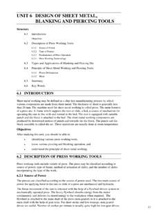
2 With external features, like shafts, the MMC is the largest size within the limits. With internal features, like holes, it is the smallest size within the limits. 56 FOOL PROOFINGE nsures that the part fits into the tool in its correct position onlyThe simplest and most cost effective method is positioning a fool proof Duplicate locatorsRedundant, or duplicate, locators should be ) Flat surface can be redundantly located. The part should be located on only one, not both, side of surfaces. b) Both the hub and the flange Locating the same parallal surface c) Difficulty with combining hole and surface location: Either locational method ( Locating from the holes or Locating from the edges) works well if used alone. 5. Motion EconomyIt involves use of easy, quick and economic loading of work of Freedom 11 Here we consider 12 degrees of freedom(not 6). 4 along each axis;2 translational and two of Movement:12 Six-pin method(3-2-1 method): Motion is restricted using clamps and three pin base can restrict five motions.
3 >Rotation about X,Y axes.(4 motions) >Translation along -ve z-axis (1 motion)Directions nine, ten and eleven are restricted by a clamping device.(3 motions)13 Locating Principles and To restrict the movement of the part around the ZZ-axis and in direction eight, two more pin-type locators are positioned in a vertical plane.(3 motions) A single pin locator in vertical plane restricts motion along direction 7.( 1 motion) So motion in all 12 directions are Six-pins- restrict nine motions. Other three are restricted by using a >>contd. This is the most common Locating method employed for square or rectangular parts. Flat bases may also be used, but these should be installed rather than machining into the base. But pin/button type locators offers more accuracy as the area of contact is less. Moreover, they raise the work above the base so that chips wont interrupt the operation. Workpieces with holes: Holes provide an excellent method for Locating . A round pin inside the hole(primary) and a diamond pin(secondary) can restrict 11 motions!
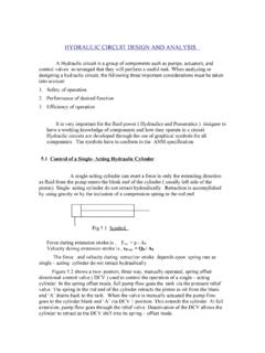
4 1617 Locating Methods: Locating from a Flat Surface:There are three primary methods of Locating work from a flat surface: solid supports adjustable supports, equalizing supports18 Solid supports: Easiest and cheapest. Less accurate. Used where machined surface acts as a Locating supports: Used where surfaces are uneven(casting, ) Threaded style is the easiest and more economical. Adjustable locators are normally used with one or more solid locators to allow any adjustment needed to level the supports: They provide equal support through two connected contact points. As one point is depressed, the other raises and maintains contact with the part. This feature is especially necessary on uneven cast from an Internal Diameter Locating a part from a hole or pattern is the most effective way to accurately position work. Nine of the twelve directions of movement are restricted by using a single pin, and eleven directions of movement are restricted with two pins. When possible, it is logical to use holes as primary part Principles and Devices2223 Locating Cylindrical Surfaces(Externally) V -locators Vee locators are used mainly for round work.
5 They can locate flat work with rounded or angular ends and flat discs. Two types:Fixed and Adjustable:24 Locating from Irregular Surfaces(External) Locating work from an external profile, or outside edge, is the most common method of Locating work in the early stages of machining. For simple components,a sighting plate may be used. Location is done by adjusting the workpiece in such a way that it has equal margins on all sides. In large parts cylindrical pins can be (irregular surfaces) If there are large variations from batch to batch, eccentric locators can be used, whose eccentricity can be varied according to the profile. Eccentricity is varied just by rotating the locator until it holds the workpiece in (cont; irregular profiles) Locating from an External Profile Nesting locators position a part by enclosing it in a depression, or recess, of the same shape as the part. Nesting is the most accurate Locating device for profile location. Obviously, the height of the nest should be lesser than the height of the workpiece.
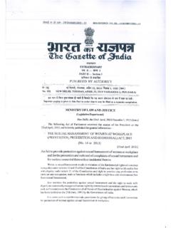
6 In case of sheet-metals or thin workpieces, finger slots or ejector pins should be and button locator locator used to support or hold the workpiece in position. Pins locators are longer and for horizontal locations. Button locators shorter,vertical locations. Locating buttons-press fit and screwed(wear and tear more replaceable)Rest pads and plates Used with heavier and larger workpiece. To support and locate the work vertically. Hold jig or fixture base plate by socket-head cap pin locator Work piece with the drilled holes use two round pins If dimension variation between centre to centre distance of the holes, one round and diamond pin locators are used Binding is eliminated Prevents movement around the pin and are relieved on two sides to allow variationNesting locator or cavity locator used to position the work piece Accurate method for profile location No need of supplementary Locating Devices But it is difficult to lift out of cavity Common types:-Ring Nest Used for cylindrical workpiece.
7 It encloses the workpieces Nest For work pieces other than cylinders. Encloses the work Nest For larger work pieces a nest may not be possible to enclose it completely. In such cases partial nests are used which encloses certain contours of the locator Sphercal location reduces contact area. Material not in direct contact with the work piece. Binding not possible in this caseSplit contact locator Relieved locator used in thick workpiece Locator is relieved in the middle Only top and bottom areas come in contact with workpieceRaised contact locator Raised contact design reducing the chance of binding Contact point is raised to the middle of the workpiece and contact area reduced Moving the contact area from the base plate reduces the effect of dirt,chip and burrsSplit pin or groove pin Used in place of dowel pins to reduce cost and time Not so accurate as they don t employ the reamed hole as in the case of dowel pinsDowel pin locator Most common type of fixed locatorCylindrical pin Used when the workpiece contains holes drilled into it Pin will bind unless centreline of the hole is perfectly aligned with cetreline of locatorMachined Fixed stop locator Used for parts that cannot be used in either a nest or V-locator Are usually machined into the tool body Since they are machined into the tool body the entire body has to be changed when locator is worn outInstalled fixed stop locator Most economical to use Since it is installed into the tool body and not machined it can be easily replaced when worn out No need to make the locator body entirely again Saves timeStandard partsjig button Commonly made from case hardening steel (16 MnCr5 or 20 MnCr5C15)
8 Have a hardness value of about 60 HRC Have a case depth of to mmJig bush Jig bushes locate and guide cutting tools Several types like linear,renewable,slip and screw bushes exist Made from direct hardening type steel such as En31,T90,20 MnV8 Hardness is usually 60 HRC with case hardened depth of to Used to remove the workpiece from close fitted locators and are present behind the workpiece Speed up the operation by reducing unloading time They are of 2 types: Mechanical type Spring plungerJig feet bolt and nuts Usually purchased as standard parts and they are built into jig body except in casting construction Jig feet is bounded with lug and grounded in order to make geometrically true surfacePressure pads Used above or below the workpiece depending on size and shape of workpiece Necessary when workpiece contains sharp corners or irregular surfaces Also used to absorb shocks Pressure for pads applied by springs,air or hydraulics Urethane pads require less space than springs since they withstand greater pressure with less deflection compared to springswasher Used for positive clamping force They should have hardness value less than the mating surface Used for compensating length in bolt sizeand to grip the clamping force C washer,swing C washer,spherical washer,lock washer ,internal star washerHand grip screws Used for positive clamping Used to tighten the part Cylindrical end,groove end.
9 Floating end are the various typesWing or fly screws used for light positive tightening Cylindrical end,groove end,floating end are the various typesQuarter turn screw Also called thumbscrew latch Designed in such a way that the operator can easily turn the screws even if the threads are covered with dry oil,dust and chips It is kept perpendicular to confirm tighteningSight Locators: Used for rough machining. Less accurate. Work fits into specific slots on the Locating plate known as sighting plates. 2 typesSight location by slots on the location by lines etched on the tool.