Transcription of SUMMIT TAPERED HIP SYSTEM
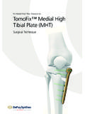
1 SUMMIT TAPERED HIP SYSTEMSURGICAL TECHNIQUE & DESIGN RATIONALEPROVEN FIXATIONF ixation is the foundation of long-term clinical success. A biocompatible titanium alloy stem, combined with POROCOAT Porous Coating and underlying radial ZTT macro texture, creates a surface that is designed for initial stability, and biologic fixation to bone. DUOFIX Stems combine POROCOAT Porous Coating, which allows for biologic fixation to bone, with the addition of a 35 micron layer of hydroxyapatite (HA) weeks8 weeks12 weeks2 DePuy Synthes Companies SUMMIT T apered Hip SYSTEM Design Rationale & Surgical TechniqueDUOFIX HA Coating 35 micron non-occluding plasma spray deposited HA coatingClinical Results 1 of 96 revised (due to fall) in a 5-year follow-up study2 Grit Blasted Distal Body Provides roughened surface engineered for supplemental stabilityPOROCOAT Porous CoatingPOROCOAT Porous Coating allows biological fixation to bone without the use of bone With more than 30 years of clinical heritage, our proprietary POROCOAT Porous Coating is composed of commercially pure titanium sintered metal Rationale & Surgical Technique SUMMIT T apered Hip SYSTEM DePuy Synthes Companies 3 Radial ZTT steps ZTT steps designed to eliminate hoop stress by directing radial force into compression.
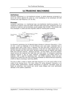
2 Provides lower risk of intra-operative fracture4**See graph on page 5 for comparison to leading competitorsADVANCED PERFORMANCEHoop stresses may increase risk of intra-operative fracture4 Radial ZTT is designed to convert hoop stresses to compression loads which may potentially reduce the risk of intraoperative Year Intra-operative Fracture Head 5 VerSys FM Taper 6,7 Synergy 8 Omnifit HA 9 SUMMIT 3 Design Rationale & Surgical Technique SUMMIT T apered Hip SYSTEM DePuy Synthes Companies 5 Direct Lateralization Enables femoral offset restoration without affecting leg length Ability to lateralize by 6mm 8mm to manage soft tissue laxity depending on stem size Offset range 30mm 50mm depending on stem sizeADVANCED BIOMECHANICS High OffsetStandard OffsetSUMMIT Dual Offset options help surgeons more effectively manage soft tissue laxity when compared to systems with only one offset DePuy Synthes Companies SUMMIT T apered Hip SYSTEM Design Rationale & Surgical Technique149 Neck Geometry Designed for a larger ROM to decrease the risk of dislocation due to secondary prosthetic impingement Provides range of motion up to 149 degrees when coupled with the PINNACLE Acetabular Cup System10 Polished Neck Decreases risk of wear
3 Debris generation, secondary to prosthetic impingementDesign Rationale & Surgical Technique SUMMIT T apered Hip SYSTEM DePuy Synthes Companies 7 ADVANCED INSTRUMENTATIONC urvedStraightStraight-longDual-offset8 DePuy Synthes Companies SUMMIT T apered Hip SYSTEM Design Rationale & Surgical TechniqueThreaded impactorStraight modular impactorCurved modular impactorOffset modular impactorBullet-tip modular impactorCompatible with the SUMMIT , CORAIL and TRI-LOCK Bone Preservation Stem Systems, the TSS Core kits feature instrumentation to facilitate the femoral preparation for anterolateral, posterior or anterior approaches. To further enhance OR flexibility, the TSS Core kits include two sets of trial heads, up to size 40mm, and can accommodate two different TSS broach CORE KITSD esign Rationale & Surgical Technique SUMMIT T apered Hip SYSTEM DePuy Synthes Companies 9 Figure 2: Cup Sizing and PositioningDetermination of Leg Length DiscrepancyPerform clinical and radiograph analysis to determine leg length management (Figure 1).
4 Figure 1: Leg Length ManagementPRE-OPERATIVE PLANNINGA cetabular Cup Sizing and PositioningUse A/P radiograph to determine acetabular component position. Use the PINNACLE Acetabular Cup SYSTEM template overlays to determine the correct implant size (Figure 2).Optimizing the position and bone contact are the main objectives in cementless acetabular the center of rotation of bearing surface on A/P vertical distance between the planned center of rotation of the acetabular component and the center of rotation of femoral head constitutes the distance the leg length will be : The targeted shell abduction (as measured on radiographs) should be 40 45 degrees taking into account each individual patient's local soft tissue and anatomic targeted shell anteversion (as measured on radiographs) should be 15 20 degrees taking into account each individual patient's local soft tissue and anatomic DePuy Synthes Companies SUMMIT T apered Hip SYSTEM Design Rationale & Surgical TechniqueFemoral Stem SelectionSelect the template that fits the proximal femur and equalizes the leg lengths.
5 The femoral template should be in-line with the long axis of femur. Mark the neck resection line at the point where the selected stem provides the desired amount of leg the chosen stem size also fits into the lateral plane and check for three point fixation (Figure 3).Figure 3: Three Point FixationDesign Rationale & Surgical Technique SUMMIT T apered Hip SYSTEM DePuy Synthes Companies 11 Figure 4: Neck OsteotomyFEMORAL NECK OSTEOTOMYA lign the neck resection guide with the long axis of the femur (Figure 4).Determine the resection level by aligning the top of the guide with the tip of the greater trochanter or measuring the pre-operatively determined distance above the lesser the resection line using electrocautery or methylene blue.*Resect the femoral head.* Tip: Make a conservative neck resection initially and use the calcar planer to DePuy Synthes Companies SUMMIT T apered Hip SYSTEM Design Rationale & Surgical TechniqueFigure 6: Box OsteotomeOption 1 Medullary Canal AccessPlace the IM initiator at the posterior margin of the neck resection laterally near the piriformis the IM initiator until sufficient circumferential clearance for the box osteotome and canal probe is achieved (Figure 5).
6 FEMORAL CANAL INITIATIONO ption 2 Box OsteotomeUse the box osteotome to enter the femoral canal at the junction of the femoral neck and greater trochanter (Figure 6). If needed the box osteotome may be used to clear bone Rationale & Surgical Technique SUMMIT T apered Hip SYSTEM DePuy Synthes Companies 13 Figure 5: Medullary Canal AccessCanal ProbingUtilize the TAPERED canal probe to establish a direct pathway to the medullary canal. Advance the probe so that the superior margin of the cutting flutes meet the neck resection (Figure 7).Note: The probe should pass easily if proper alignment has been : Circumferential clearance of the probe is important to avoid reaming in the varus PREPARATIONF igure 8 Figure 7: Canal ProbingLateralizingAlignment Verification and Lateralizing The path established by the canal probe will dictate the route for trochanteric reaming, TAPERED reamers and : It is important to gain neutral alignment of the reaming (lateralizing) may be used to lateralize the proximal entry point for the TAPERED reamers; broaches aid in neutral stem alignment (Figure 8).
7 Correct AlignmentIncorrect Alignment11 DePuy Synthes Companies SUMMIT T apered Hip SYSTEM Design Rationale & Surgical TechniqueTapered ReamingSequential Ream starting 2 3 sizes below the pre-operatively templated size. Example: If the hip pre-operatively templated for a size 6 implant then TAPERED reaming would begin with the size 2 3 reamer and progress to the size 6 7 reamer. Each reamer has dual depth calibration lines for each of the two stem sizes, distally located for calcar referencing and proximally for greater trochanter referencing (Figure 9). TAPERED REAMINGF igure 9: TAPERED ReamingDesign Rationale & Surgical Technique SUMMIT T apered Hip SYSTEM DePuy Synthes Companies 15 FEMORAL BROACHINGF igure 10: Femoral BroachingStraightStraight-longCurvedDual -offsetBroaching the FemurWith the broach oriented laterally towards the greater trochanter, broach sequentially starting 2 3 sizes below the pre-operatively templated is one broach for every implant size.
8 During sequential broaching, the broach may become difficult to remove, therefore the broach extractor is recommended. The final broach should fit and fill the proximal femur with the top of the cutting teeth at the desired neck resection. This final broach should feel rotationally : If the femur was reamed to a size 6, it should then be broached to a size 6 and assessed for axial and rotational : The SUMMIT Instrumentation is designed to prepare the femur line-to-line. The porous-coated region of the femoral component is oversized by per side relative to the instrumentation. If the broach size is countersunk more than 4mm below the neck resection, re-evaluate the resection level. If the neck resection level is determined to be correct, the next larger size broach is DePuy Synthes Companies SUMMIT T apered Hip SYSTEM Design Rationale & Surgical TechniqueTRIAL REDUCTIONC alcar Planing/MillingCalcar planing is a definitive landmark for stem insertion by milling a precise resection the planer over the broach stud and mill the calcar to the broach face (Figure 11).
9 Note: Make sure the planer is rotating prior to engaging the 12: Trial ReductionFigure 11: Calcar Planing / MillingTrial ReductionStandard and high offset neck segments and trial modular heads are available to assess proper component position, joint stability and range of motion (Figure 12).Trial heads are color coded to indicate different neck offsets. The brown +5 head is the neutral head and doesn t change the offset of the ExtractionUse the broach handle or broach extractor to remove the final Rationale & Surgical Technique SUMMIT T apered Hip SYSTEM DePuy Synthes Companies 17 FINAL IMPLANTATIONStem Inserter OptionsStem inserters with various geometries are available to enable the many surgical approaches for hip replacement. The retaining stem inserter can be used if a positive connection between the implant and instrument is required (Figure 13).Figure 13: Stem InsertersFigure 14: Final ImplantationThreadedStraight modularCurved modularOffset modularBullet-tip modularFinal ImplantationSelect the stem size that corresponds to the final broach.
10 Introduce the implant into the femoral canal by hand and orient the implant with proper alignment and version. Using moderate mallet blows, advance the stem into position. In the area of POROCOAT Porous Coating, the implant is oversized by per side relative to the broach. Excessive force should not be needed to seat the stem. The implant is fully seated when the top of the POROCOAT Coating reaches the level where the face of the broach previously sat and the implant is stable (Figure 14). It is possible for the implant to be seated and stable and still display 2 3 rows of POROCOAT Coating proximally (Figure 14).18 DePuy Synthes Companies SUMMIT T apered Hip SYSTEM Design Rationale & Surgical TechniqueFemoral Head ImpactionFollowing the final trial reduction, clean and dry the taper to ensure it is free of debris. Place the appropriate femoral head onto the taper. Using the head impactor, engage the head with light taps.