Transcription of SUNLINE 2000 GAS / ELECTRIC SINGLE PACKAGE …
1 GENERALYORK Model DCG units are SINGLE PACKAGE air conditionerswith gas heat designed for outdoor installation on a rooftop ora units are completely assembled on rigid, permanentlyattached base rails. All piping, refrigerant charge, and electricalwiring is factory installed and tested. The units require onlyelectric power and duct connections at the point of gas-fired heaters have aluminized steel tubular heatexchangers and spark ignition with proven soon as a unit is received, it should be inspected for possibledamage during transit. If damage is evident, the extent of thedamage should be noted on the carrier s freight bill. A separaterequest for inspection by the carrier s agent should be made inwriting. Refer to Form for additional information on the design, installation, operation andservice of this equipment is available in the following referenceforms: - General Installation - Pre-start & Post-start Check List - Economizer Accessory - Motorized Outdoor Air Damper Accy.
2 - Gas Piping Accessory - Propane Conversion Accessory (USA) - High Altitude Accessory (Nat. Gas) - High Altitude Accessory (Propane) - Propane Conversion Accessory (CAN.) - Low Ambient AccessoryRenewal Parts: Refer to the Renewal Parts Manual for complete listing ofreplacement parts on this forms referenced in this instruction may be ordered from:Publications Distribution CenterUnitary Products Box 1592, York, Pa. 17405 APPROVALSD esign certified by & CGA as follows:1. For use as a forced air furnace with cooling For outdoor installation For installation on combustible For use with natural gas or propane gas. SUNLINE 2000 GAS / ELECTRICSINGLE PACKAGE AIR CONDITIONERSINSTALLATION INSTRUCTIONS upersedes: (693) (995)MODELS D3CG090, 102, 120 (STYLE B) & D4CG150 (STYLE A)( EER)035-13092 CAUTIONTHE ENCLOSED INSTALLATION INSTRUCTIONS AND ANY APPLICABLELOCAL, STATE, AND NATIONAL CODES INCLUDING, BUT NOT LIMITEDTO, BUILDING, ELECTRICAL, AND MECHANICAL IS P RO DU C T M US T B E IN S TALLED IN S TR ICT C O M P LIA N C E W ITHWARNINGOPERATION OF THE PRODUCT COULD CAUSE PERSONAL INJURYOR PROPERTY INSTALLATION MAY CREATE A CONDITION WHERE THE208/230/575 VOLTMODELS ONLY208/230/460 VOLTMODELS ONLY FOR YOUR SAFETYDo not store or use gasoline or other flammablevapors and liquids in the vicinity of this or anyother appliance.
3 FOR YOUR SAFETYIf you smell gas:1. Open Don t touch electrical switches3. Extinguish any open Immediately call your gas should pay particular attention to the words: NOTE, CAUTION and WARNING. Notes are intended to clarify or makethe installation easier. Cautions are given to prevent equipment damage. Warnings are given to alert installer that personal injuryand/or equipment damage may result if installation procedure is not handled .. 1 Reference .. 1 Approvals .. 2 INSTALLATIONL imitations .. 3 Location .. 3 Rigging and Handling .. 3 Clearances .. 3 Ductwork .. 3 Barometric Relief / Fixed Outdoor Air Intake Damper 4 Condensate Drain .. 4 Filters .. 4 Service 4 Thermostat .. 4 Power and Control 4 Combustion Discharge .. 5 Gas Piping .. 5 Gas Connection .. Units, Tanks and Piping .. 6 Vent and Combustion Air 6 Optional Economizer / Mot. Damper Rain Hood .. 6 OPERATIONC ooling 12 Preliminary Operation 12 Cooling Sequence of Operation.
4 12 Safety Controls (Cooling).. 12 Heating Sequence of Operation .. 12 Safety Controls (Heating) .. 13 Heat Anticipator Setpoints .. 13 Pre-Start Check 13 START-UPOperating 14 Post-Start Check List .. 14 Manifold Gas Pressure Adjustment .. 14 Pilot 14 Burner 14 Burner Air Shutter Adjustment .. 15 Checking Supply Air 15 Adjustment of Temperature Rise .. 16 Checking Gas Input .. 16 Secure Owner s Approval .. 16 MAINTENANCE & TROUBLESHOOTINGN ormal 17 Cleaning Flue Passages and Heating Elements .. 17 Troubleshooting .. 18 Replacement Parts .. 19 TABLES No. Description Page1 Unit Application Data ..32 Gas Heat Application Sizing ..54 Physical Data ..85 Supply Air Blower Perf. 7-1/2 - 10 Air Blower Perf. 12-1/2 Ton ..117 Accessory Static Resistances ..118 Blower Motor and Drive Data ..119 Electrical Control Setting ..1311 Blower Motor Pulley Rate - Cubic Feet Per Hour.
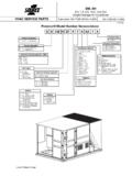
5 16 FIGURES No. Description Page1 Center of Relief / Fixed Outdoor Air Intake Damper Drain Field Supply Connection ..66 Bottom Supply Connection ..67 Vent and Combustion Air / Mot. Damper Hood Assembly ..79 Adjusting Enthalpy and Valve Gas Valve ..1413 Proper Flame Adjustment ..1414 Typical Flame Appearance ..1515 Pressure Drop versus Supply Air OF CONTENTSD3CG3 NPRODUCT NOMENCLATUREPRODUCT GENERATION3 = 3rd Generation4 = 4th GenerationPRODUCT CATEGORYD = SINGLE PACKAGE Air Conditioner (Air Cooled)PRODUCT IDENTIFIERCG = Gas/ElectricVOLTAGE CODE25 = 208/230-3-6046 = 460-3-6058 = 575-3-60 NOMINAL GAS HEATINGOUTPUT CAPACITY090 = 7-1/2 Ton102 = 8-1/2 Ton120 = 10 Ton150 = 12-1/2 Ton1090025 FACTORY INSTALLEDHEATN = Gas Heat InstalledNOMINAL COOLINGCAPACITY130 = 130 MBH165 = 163 MBH200 = 198 Products GroupLIMITATIONST hese units must be installed in accordance with the followingnational and local safety codes:In :1.
6 National Electrical Code ANSI/NFPA No. National Fuel Gas Code Gas-Fired Central Furnace Standard ANSI Local gas utility Canada:1. Current Canadian Electrical Code Current Gas Installation Codes and . Local plumbing and waste water Other applicable local codesRefer to Table 1 for Unit Application Data and to Table 2 for GasHeat Application installation, the unit must be adjusted to obtain atemperature rise within the range specified on the unit components are to be added to a unit to meet local codes,they are to be installed at the dealer s and/or the customer of unit for proposed installation should be based on heatloss/heat gain calculation made according to the methods ofthe Air Conditioning Contractors of America (ACCA).This furnace is not to be used for temporary heating of buildingsor structures under the following guidelines to select a suitable location forthese Unit is designed for outdoor installation Condenser must have an unlimited supply of air.
7 Where achoice of location is possible, position the unit on eithernorth or east side of : Excessive exposure of this furnace to contami-nated combustion air may result equipment dam-age or personal injury. Typical contaminatesinclude: permanent wave solutions, chlorinatedwaxes and cleaners, chlorine based swimmingpool chemicals, water softening chemicals, carbontetrachloride, Halogen type refrigerants, cleaningsolvents ( perchloroethylene), printing inks,paint removers, varnishes, hydrochloric acid, ce-ments and glues, antistatic fabric softeners forclothes dryers, masonry acid washing For ground level installation, use a level concrete slab witha minimum thickness of 4 inches. The length and widthshould be at least 6 inches greater than the unit base not tie slab to the building Roof structure must be able to support the weight of the unitand its options and/or accessories.
8 Unit must be installedon a solid level roof curb or appropriate angle iron : If a unit is to be installed on a roof curb orspecial frame other than a YORK roof curb,gasketing must be applied to all surfaces thatcome in contact with the unit Maintain level tolerance to 1/2" maximum across the entirelength or width of the AND HANDLINGE xercise care when moving the unit. Do not remove anypackaging until the unit is near the place of installation. Rig theunit by attaching chain or cable slings to the lifting holesprovided in the base rails. Spreaders, whose length exceedsthe largest dimension across the unit, MUST be used acrossthe top of the LIFTING A UNIT, MAKE SURE THAT ITS WEIGHT ISDISTRIBUTED EQUALLY ON THE CABLES SO THAT IT WILL may also be moved or lifted with a forklift. Slottedopenings in the base rails are provided for this OF FORKS MUST BE A MINIMUM OF 54".
9 Remove the nesting brackets from the four corners on top ofthe unit. All screws that are removed when taking thesebrackets off must be replaced on the : An adhesive backed label is provided over theoutside of the combustion air inlet opening to pre-vent moisture from entering the unit which couldcause damage to electrical components. Allow thisclosure label to remain in place until the combus-tion air hood is to be installed (refer to Figure 7).Refer to Table 4 for unit weights and to Figure 1 for approximatecenter of units require certain clearances for proper operation andservice. Installer must make provisions for adequatecombustion and ventilation air in accordance with Section ,Air for Combustion and Ventilation of the National Fuel GasCode, ANSI (in ) or Sections , or ofGas Installation Codes and .2 (in Canada)and/or applicable provisions of the local building codes.
10 Referto Figure 10 for the clearances required for combustibleconstruction, servicing, and proper unit : Do not permit overhanging structures or shrubs toobstruct outdoor air discharge outlet, combustionair inlet or vent should be designed and sized according to themethods in Manual Q of the Air Conditioning Contractors ofAmerica (ACCA).A closed return duct system shall be used. This shall notpreclude use of economizers or outdoor fresh air intake. Thesupply and return air duct connections at the unit should bemade with flexible joints to minimize supply and return air duct systems should be designed forthe CFM and static requirements of the job. They should NOTbe sized to match the dimensions of the duct connections onthe : When fastening ductwork to side duct flanges onunit, insert screws through duct flanges only. DONOT insert screws through ductwork must be insulated and ri a ti on Min.