Transcription of Symmetrical Monopole VSC Transmission - …
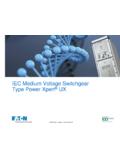
1 25 March 2014. Symmetrical Monopole VSC Transmission By Dennis Woodford Background The VSC configuration of the future will be Modular Multi-level Converter (MMC). Converter technology is a fast moving technology and this is a summary of the present state of the art with the Symmetrical Monopole configuration shown simply in Figure 1: Figure 1: (a) Symmetrical Monopole that is ungrounded (or high resistance grounded). The interface transformers for the Symmetrical Monopole option in Figure 1 are single, conventional two-winding transformers with the secondary (valve side) windings ungrounded or high resistance grounded, or if star configured, connected to ground through a bank of surge arresters conne4cted to the star The main disadvantage of the Symmetrical Monopole configuration in Figure 1, compared to a bipole option, is loss of redundancy with a permanent line or cable fault.
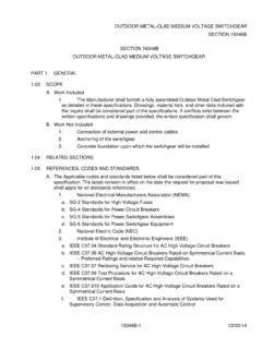
2 For a single pole-to-ground fault for the ungrounded Symmetrical Monopole of Figure 1, no power transfer is lost during the fault since load current still flows and pole-to-pole voltage stays the same, while the voltage of the un-faulted pole jumps to two per-unit. No surge of fault current flows through the VSC converters. An example of pole voltage with application of a single pole-to-ground fault is shown in Figure 2. Electranix Corporation, 12 75 Scurfield Blvd, Winnipeg, MB R3Y 1G4, Canada. Figure 2: Impact of pole voltage on an ungrounded Symmetrical VSC Monopole with a pole-to-ground fault simulation The two-per-unit voltage on the un-faulted pole applies excessive stress to a cable if it is not qualified to withstand such voltage. If the pole-to-ground fault is temporary, as from lightning on an overhead line, then when the lightning strike dissipates, the arc of the pole fault will also dissipate.
3 If the pole fault is in a cable, and therefore permanent, then the dc line is cleared by the ac circuit breakers at the VSC converters at each end of two terminal Transmission . Even when the Symmetrical Monopole has been completely disconnected from the ac system, the un-faulted cable will still retain excessive overvoltage and must be de- energized as quickly as possible. This can be accomplished by switching to the cable a discharge resistor or by applying a solid-state switch with a discharge resistor in the form of a dynamic breaking resistor (DBR) or DC Chopper, as it is sometimes known. A DC. Chopper, or DBR, is shown in Figure 3. The two-per-unit overvoltage on the un-faulted pole must be returned to per unit voltage as quickly as possible so that the overvoltage affects pole insulation more as a switching surge than a steady state, two-per-unit overvoltage in order to decrease the possibility of this un-faulted pole from generating its own fault 2.
4 Figure 3: Location of a DC Chopper in a VSC feeder If an ungrounded or high resistance grounded Symmetrical MMC Monopole is configured for an overhead dc line, it may be subject to frequent pole faults caused by lightning. After a time to allow for fault arc dissipation and de-ionization of the arc path, the DBR. or chopper can quickly re-balance the pole voltages. No fault-clearing action by switches or circuit breakers is necessary, during which time dc power will continue to flow. This allows for the possibility that shield wires are unnecessary. Half Bridge and Full Bridge Sub-modules The basic configurations of half bridge and full bridge sub-module that can be building blocks for an MMC converter are shown in Figure 4. 3. Figure 4: Half bridge and full bridge sub-modules for use in MMC converters Consider the MMC converter operating with half-bridge sub-modules that are individually controlled.
5 With two IGBTs per sub-module, there are three states. With reference to Figure 5, with two IGBTs, IGBT1 and IGBT2, the three states are: Figure 5: Half bridge operating states (courtesyof Siemens). 4. Each of the sub-modules is individually controlled in order to generate the stepped voltage wave shape shown in Figure 6. Together, the assembly of modules synthesizes the desired ac voltage waveform of the required phase and magnitude, noting of course that the peak-to-peak ac voltage magnitude cannot be greater than the dc voltage applied. Figure 6: An MMC converter made up of sub-modules and the resulting ac voltage waveshape generated by selective switching of the sub-modules. There is another sub-module configuration known as the Three Step Ladder . It is equivalent to two full bridge sub-modules in series but with 6 instead of 8 IGBT/Diode switches as shown in Figures 7 and 8.
6 In Table 1 all the logic switching states for the three step ladder sub-module are shown. Although there are less switches and consequently less losses compared to the two full bridge sub-modules, this configuration is more challenging to modularize. 5. Figure 7: a) Three step ladder sub module b) Two full bridge sub-modules for comparison Figure 8: Three step ladder operation a) for zero voltage level, b) Operationat 2*Vdc, and 3) Operation for voltage level at Vdc 6. Table 1: All the logic switching states for the three step ladder sub-module The three step ladder sub-module for VSC Transmission was developed by Electranix Corporation and is in the public domain. With the series connection of half-bridge sub-modules in the MMC configuration, as shown in Figure 6, it is not possible for the Voltage-Sourced Converter to prevent dc side fault current from flowing through the converter from the ac system.
7 Blocking the IGBTs converts the converter into a diode bridge, which passes uncontrolled fault current through to the dc side fault from the ac system. Such a fault is generally cleared by opening the ac circuit breakers that passes the ac fault current through the converter to the dc side fault. There is anticipation that high-speed dc circuit breakers will be available in due course to allow clearing of a dc side fault without opening the ac circuit breakers. Use of high-speed dc circuit breakers will be a great advantage in clearing dc side faults on dc grids. All the major HVDC equipment suppliers are developing high-speed dc circuit breakers. When full-bridge sub-modules are connected in the MMC configuration of Figure 13 4, the converter output voltage can be either polarity and not fixed polarity, as when the MMC converter is constructed with half-bridge sub-modules.
8 Through controlled polarity reversal of full-bridge sub-modules in the MMC configuration, the output dc voltage can be reduced so that dc side fault currents can be suppressed. This may obviate the need for high-speed dc side circuit breakers, so that basic mechanical switches can be used when dc side fault current is reduced to zero by the judicious control of the full-bridge sub- modules in the MMC converters. The disadvantage of the full-bridge sub-modules compared with half-bridge sub-modules is that losses are greater since the sub-module current path is through two IGBT and diode switches in series, and only through one IGBT and diode switch for the half-bridge sub-module. The main components for a single sub-module, in addition to the oil-free capacitor, include: 7.
9 1. IGBTs with reverse-biased diodes where two are required for the half bridge and four for the full bridge, all mounted on water-cooled heat sinks 2. Protective thyristor usually for the half-bridge sub-module only 3. Gate drive units for the IGBTs 4. Fast mechanical by-pass switch across the terminals of the sub-module to short it out in the event of a failure of an IGBT to open the circuit across the capacitor 5. Laminated conductors for low-inductance connections Full-bridge converters result in higher converter costs (approximately 20% more to the converter station) as compared to half bridge, along with higher losses (approximately to , as compared to approximately for half-bridge). There is the possibility to populate the valve arms in a VSC valve group with a combination of half-bridge and full-bridge sub-modules to lower DC voltage.
10 Protection of DC Systems with Symmetrical Monopole Converters A possibility for protection of DC systems with ungrounded or high resistance grounded Symmetrical monopoles with half bridge sub-modules when they are subject to single pole to ground DC side faults, is a control action. The power flow through the DC system will continue with one pole faulted to ground but the DC side voltage will displace as shown in Figure 2 with the un-faulted pole at per unit. The fault on the DC system can be cleared with opening of the AC circuit breakers at the converters feeding into the faulted cable section as mentioned above. If the DC system is a DC grid and the fault is a permanent one, then the AC breakers at all converters feeding into or out of the grid must open shutting down the grid.