Transcription of Synchro and Resolver Engineering Handbook
1 SyncSyncSyncSyncSynchrhrhrhrhro and Ro and Ro and Ro and Ro and ResolvesolvesolvesolvesolverererererEngi neering HandbookEngineering HandbookEngineering HandbookEngineering HandbookEngineering HandbookWe have been a leader in the rotary componentsindustry for over 50 years. Our staff includes electrical,mechanical, manufacturing and software engineers,metallurgists, chemists, physicists and materialsscientists. Ongoing emphasis on research andproduct development has provided us with theexpertise to solve real-life manufacturing state-of-the-art tools in our complete analyticalfacility, our capabilities include a full range ofenvironmental test, calibration and Components Group places a continuingemphasis on quality manufacturing and productdevelopment to ensure that our products meet ourcustomer s requirements as well as our stringentquality goals.
2 Moog Components Group has earnedISO-9001 look forward to working with you to meet yourresolver North Main Street, Blacksburg, VA 24060-3127800/336-2112 ext. 279 540/552-3011 FAX 540/557-6400 e-mail: and information are subject to change without prior notice. 2004 Moog Components Group Inc. MSG90020 12/04 and Resolver Engineering Handbook ContentsPageSection and of Operation and Classic Control Transolver and Differential Linear Synchros and Electromagnetic Hairspring Flex Lead Type2-6 Section and Resolver Voltage and (Electrical Error) Ratio and Phase Current and Input Withstanding T Parameters vs.
3 (Electrical Error) , Input Current and Input Voltages4-2 Section Parameters and Mounting Considerations - Housed Considerations - Unhoused of Improper Mounting5-2 PageSection Synchros and vs. Ratio vs. Air and Test Reluctance Components6-4 Section to Digital Measurement Transmission Using Direct Angle Phase Analog Sampling Tracking Resolver to Digital Dual R/D Converter Commutation of brushless Resolver to Digital Synchronous Demodulation7-5 Section , Environmental Requirements,and Military Requirements and Military Specifications8-1 Section.
4 Handling and and and Terminology10-1 Appendix AMultispeed Ratio TableA-1 Appendix BBinary to Angular Conversion TableB-1 Appendix CMoog Components Group Synchro and ResolverPerformance ParametersC-1 Pancake Resolvers and SynchrosC-2 through C-5(Single and Multispeed Types)Legend of Parameters and AbbreviationsC-6 Pancake Linear TransormersC-7 Housed brushless , Single Speed Size 8C-8 Housed brushless , Single Speed Size 11C-9 Synchros and resolvers have performed as part ofelectromechanical servo and shaft angle positioningsystems for over 50 years. With experience, themarket place has come to realize that, in conjunctionwith appropriate interface electronics, a Synchro orresolver can form the heart of an outstanding digitalshaft angle measurement and positioning system.
5 Thetechnology has been developed and the systemsbased on it are unsurpassed in reliability and Handbook was written by the Moog ComponentsGroup Engineering staff, inspired by questions fromengineers working in the most sophisticated militaryand space programs. Many of our products wereoriginally designed as state-of-the-art units. Somehave since become standards. The engineeringexpertise of Moog Components Group is apparent inour participation in all manned spaced missions,many strategic missile programs, and our reputationin the five decades, Moog Components Group has alsobeen involved in the design, development, andproduction of rotating components for commercial,industrial and medical applications.
6 Our synchros andresolvers include conventional and pancake can be provided as brushless and/ormultispeed units. Moog Components Group is also aleading manufacturer of brush and brushless DCmotors. Our machine shops contain modernequipment to produce precision components for barand strip stock. Our in-house capability for makinglamination dies enables us to quickly change thenumber of slots and inside and/or outside diameters,to suit virtually any design components described in this Handbook are justa small selection from a broad spectrum of devicesthat we manufacture. Dedicated people, with yearsof experience in manufacturing products with highstandards, staff all of our maintain a network of sales offices across theUnited States and Internationally.
7 Our staff engineersare available to support your design efforts or to workas part of your proposal look forward to working with you to meet yourcomponent Synchros and Resolvers is the rotor position angle. VS1-3 is the voltagefrom the S1 terminal to the S3 terminal. All othervoltages are similarly defined throughout stator voltages are either approximately intime phase or 180 out of time-phase with theapplied voltage. The amount by which the outputvoltages differ from an exact 0 or 180 time-phaserelationship with the input voltage is known as thesynchro (time) phase a Synchro operating at 400 Hz working intoan open circuit, the output voltage will always leadthe input voltage by a few degrees (8 to 20 forsmall sizes; 2 to 8 for larger sizes).
8 The transmitter equations show that no where overthe entire 360 rotation of the rotor will the sameset of stator voltages appear. The transmitter,therefore, supplies information about the rotorposition angle as a set of three output convert this information, it is necessary to usean instrument which will measure the magnitudeof these voltages, examine their time-phaserelationships, and return them to their original form:a shaft position. Such a device is the synchroreceiver (CR). These two units form the most basicsynchro ReceiverThe construction of the receiver is electricallyidentical to that of the transmitter.
9 The outputvoltages vary with rotor position in the samemanner as those of the transmitter. In use, thereceiver is connected back-to-back with atransmitter. Like-numbered terminals areconnected together (see Figure ) and therotors are excited in parallel. At the instant thesystem is energized, voltage differences existacross each pair of stator windings if the rotors ofthe units are not at the exact same angle relativeto the stator phases . This causes current to flowin both stators, producing a torque on each Theory of Operation and Classic ApplicationsA Synchro functions as an electromechanical transducerwhich, as a circuit element, is essentially a variablecoupling transformer.
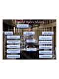
10 The magnitude of the magneticcoupling between the primary and secondary variesaccording to the position of the rotating element. This inturn varies the magnitude of the output voltage. In somesystems, a mechanical input, such as a shaft rotation, isconverted to a unique set of output voltages. In others, aset of input voltages is used to turn a Synchro rotor to adesired can be classified in two overlapping groups:torque synchros and control synchros include transmitters (CG), differentials(CD) and receivers (CR).Control synchros include transmitters (CG), differentials(CD) control transformers (CT), resolvers (CS), lineartransformers (LT) and the two hybrid units: transolvers(CSD) and differential resolvers (CDS).