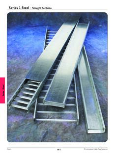
Transcription of T&B CABLE TRAY METALLIC CABLE TRAY
1 A 32 T & B C A B L E T R AY M E TA L L I C C A B L E T R AY. e e e e A LU M I N U M C A B L E T R AY A 33. H. Aluminum CABLE tray Overview B. Features Accessories B. Straight side rail design: Extruded I-beam; Each pair of splice plates comes with nominal height 4 in. to 8 in.; loading height 3. 8 in. mounting hardware 3 in. to 7 in. Complete line of accessories and Snap-in splice plate connection support systems Reverse position of every other rung for B. bottom or top mounting of CABLE ties Material Versatile continuous open slot rungs 6063 aluminum alloy (strut profile). Holes spaced 1 in. designed based on the Compliance exclusive Ty-Rap CABLE tie slots (5 8 x 5 8) CSA, NEMA, NEC, UL. Extra wide rung Four bolt connection Load ratings Choice of two styles of fitting (U and H) side rails safety factor. All tray sections will support an additional 200 lb concentrated load on any Applications portion of tray (side rail, rung, etc.) above Commercial: Industrial: and beyond published load class.
2 Schools Petrochemical plants Hospitals Automotive plants Office buildings Paper plants Airports Food processing Casinos Power plants Stadiums Refineries Manufacturing Mining A 34 T & B C A B L E T R AY M E TA L L I C C A B L E T R AY. e . Aluminum CABLE tray Straight lengths . e tray bottom types: ladder , ventilated and solid trough e ladder E xtra wide aluminum rungs are welded to extruded aluminum I-beam side rails. Every second rung is reversed to allow for easy top or bottom mounting of CABLE ties and clamps. All edges and welds are e rounded and smooth to prevent CABLE damage. Ventilated*. A fabricated structure consisting of integral or separate longitudinal rails and a bottom having openings sufficient for the passage of air and utilizing 75% or less of the plan area of the surface to support cables. The maximum open spacings between CABLE support surfaces of transverse elements do not exceed 102 mm (4 in.) in the direction parallel to the tray side rails (rung edge to rung edge).
3 Solid trough**. A fabricated structure consisting of a bottom without ventilation openings within separate longitudinal side rails.. * For load CSA class C/3M, ** Fast and easy snap-in NEMA 8C or less, please splice plates are provided see alternative ventilated with each straight section. series of CABLE tray called One-Piece found on pages A174 to A207 of the catalogue. A LU M I N U M C A B L E T R AY A 35. H. Straight lengths number selection How to create part numbers Methods ABB has created a numbering system based on the 1. Select the material best suited to your order of selection criteria. For example, the first environment. Refer to technical section page A9. selection issue is the environment to which the 2. Determine the tray series using the NEMA/CSA B. CABLE tray will be subjected. This selection will load/span designations page A16, and sizing lead to the best material for your application. CABLE tray page A23. For complete details on the CABLE tray selection 3.
4 Select nominal depth and width of tray based on process, see page A9 in the technical section. CABLE loading. See sizing CABLE tray page A23. 4. Select the bottom type based on cables and B. spacing requirements. 5. The last number is the length of the CABLE tray in meters or inches. B. (A H 1 - 6) 24 - L09 - 144. Material prefix Series Side rail height (in.) Width (in.) Bottom type Aluminum A Series 1 ** 1 4" 4 6 ** 06 6" rung spacing L06. 9 09 9" rung spacing L09. Series 3 3. 12 12 12" rung spacing L12. Series 5 5. 18 18 Ventilated ** V. Series 2 2 5" 5 24 24 Solid trough ** S. Style prefix Series 4 4 30 30. H-Beam H. Series 1 1 6" 6 36 36. Series 3 3 42 42. Length Series 4 4. 12 ft. 144. Series 5 5. 24 ft. 288. Series 6 6 3 meters 3. Series 7 7 6 meters 6. Series 3 3 7" 7 30 ft. 360. Series 4 4 40 ft. 480. Series 1** 1 8" 8. ** Fittings not available for 8 in. side rail series 1.. ** For load CSA Class C/3M, NEMA 8C or less, please see an alternative ventilated series of CABLE tray called One-Piece found on pages A174 to A207.
5 Of this catalogue. Not offered in 40 ft. length.. For series 76, 47. and 18 only.. Only offered with series 1, 8 in. side rail height, width between 12 to 36 in. A 36 T & B C A B L E T R AY M E TA L L I C C A B L E T R AY. e . Aluminum straight lengths 4 in. Straight sections/series 1-4 ladder , ventilated and solid trough e Technical specifications All calculations and data are based on 42 in. wide CABLE trays with rungs spaced on 12 in. centers with tray supported as simple spans with deflection measured at the midpoint. Continuous spans may e reduce deflection by as much as 50%. Deflection factor: For lighter loads, deflection can be calculated by multiplying the load by the deflection factor. e . 4 in. Straight sections/series 1-4 ladder , ventilated and solid trough Support span (feet). Series 6 8 10 12 14 16 18 20. AH1-4 Load (lb)/ft.) 300 169 108 75 . Deflection (in.) . Deflection factor .. Straight section number selection (A H 1 - 4) 24 - L09 - 144.
6 Material prefix Style prefix Series Side rail Width (in.) Bottom type Length Aluminum A H-Beam H Series 1 ** 1 height (in.) 6 06 6 in. rung spacing L06 12 ft. 144. 4 4 9 09 9 in. rung spacing L09 24 ft. 288. 12 12 12 in. rung spacing L12 3 meters 3. 18 18 Ventilated ** V 6 meters 6. 24 24 Solid trough S. 30 30. 36 36. 42 42.. ** Series 1 is available in 12 ft. or less.. ** For load CSA class C/3M, NEMA 8C or less, please see an alternative ventilated series of CABLE tray called One-Piece found on pages A174 to A207 of this catalogue.. For fittings, consult pages A48 to A98. A LU M I N U M C A B L E T R AY A 37. H.. B. Dimensions AH1-4. W (in.) Wo (in.) Wi (in.). Wo 6 B. 9 Wi 12 18 W. 24 30 B. 36 42 Technical specifications Load ratings: safety factor. All tray sections will support an additional 200 lb concentrated load on any portion of tray (side rail, rung, etc.) above and beyond published load class.. Load ratings: safety factor Side rail design Classifications Series factors 1 pair NEMA CSA UL.
7 AH1-4 AH1-4 Ix = in. 4. 12B, 8C C/3m UL cross Sx = sectional area: Area = A 38 T & B C A B L E T R AY M E TA L L I C C A B L E T R AY. e . Aluminum straight lengths 4 in. Straight sections/series 3-4, 5-4 ladder , ventilated and solid trough e Technical specifications All calculations and data are based on 42 in. wide CABLE trays with rungs spaced on 12 in. centers with tray supported as simple spans with deflection measured at the midpoint. Continuous spans may e reduce deflection by as much as 50%. Deflection factor: For lighter loads, deflection at any length can be calculated by multiplying the load by the deflection factor. e . 4 in. Straight sections/series 3-4, 5-4 ladder , ventilated and solid trough Support span (feet). Series 6 8 10 12 14 16 18 20. AH3-4 Load (lb)/ft.) 567 319 204 142 104 80 63 51. Deflection (in.) Deflection factor AH5-4 Load (lb)/ft.) 1044 588 376 261 192 147 116 94. Deflection (in.) Deflection factor . Straight section number selection (A H 5 - 4) 24 - L09 - 144.
8 Material prefix Style prefix Series Side rail Width (in.) Bottom type Length Aluminum A H-Beam H Series 3 3 height (in.) 6 06 6 in. rung spacing L06 12 ft. 144. Series 5 5 4 4 9 09 9 in. rung spacing L09 24 ft. 288. 12 12 12 in. rung spacing L12 3 meters 3. 18 18 Ventilated V 6 meters 6. 24 24 Solid trough S. 30 30. 36 36. 42 42.. For fittings, consult pages A48 to A98. A LU M I N U M C A B L E T R AY A 39. H.. B. Dimensions AH3-4 AH5-4. W (in.) Wo (in.) Wi (in.) Wo (in.) Wi (in.). Wo 6 B. 9 Wi 12 18 W 24 30 B. 36 42 Technical specifications Load ratings: safety factor. All tray sections will support an additional 200 lb concentrated load on any portion of tray (side rail, rung, etc.) above and beyond published load class.. Load ratings: safety factor Side rail design Classifications Series factors 1 pair NEMA CSA UL. AH3-4 AH3-4 Ix = 12C, 16B D/6m UL cross Sx = sectional area: Area = AH5-4 Ix = 20B, 16C E/6m UL cross Sx = sectional area: Area = AH5-4.
9 A40 T & B C A B L E T R AY M E TA L L I C C A B L E T R AY. e . Aluminum straight lengths 5 in. Straight sections/series 2-5, 4-5 ladder , ventilated and solid trough e Technical specifications All calculations and data are based on 42 in. wide CABLE trays with rungs spaced on 12 in. centers with tray supported as simple spans with deflection measured at the midpoint. Continuous spans may e reduce deflection by as much as 50%. Deflection factor: For lighter loads, deflection at any length can be calculated by multiplying the load by the deflection factor. e . 4 in. Straight sections/series 3-4, 5-4 ladder , ventilated and solid trough Support span (feet). Series 6 8 10 12 14 16 18 20. AH2-5 Load (lb)/ft.) 556 313 200 139 102 78 62 50. Deflection (in.) Deflection factor AH4-5 Load (lb)/ft.) 900 506 324 225 165 127 100 81. Deflection (in.) Deflection factor . Straight section number selection (A H 2 - 5) 24 - L09 - 144. Material prefix Style prefix Series Side rail Width (in.
10 Bottom type Length Aluminum A H-Beam H Series 2 2 height (in.) 6 06 6 in. rung spacing L06 12 ft. 144. Series 4 4 5 5 9 09 9 in. rung spacing L09 24 ft. 288. 12 12 12 in. rung spacing L12 3 meters 3. 18 18 Ventilated V 6 meters 6. 24 24 Solid trough S. 30 30. 36 36. 42 42.. For fittings, consult pages A48 to A98. A LU M I N U M C A B L E T R AY A41. H.. B. Dimensions AH2-5 AH4-5. W (in.) Wo (in.) Wi (in.) Wo (in.) Wi (in.). Wo 6 B. 9 Wi 12 18 W. 24 30 B. 36 42 Technical specifications Load ratings: safety factor. All tray sections will support an additional 200 lb concentrated load on any portion of tray (side rail, rung, etc.) above and beyond published load class.. Load ratings: safety factor Side rail design Classifications Series factors 1 pair NEMA CSA UL. AH2-5 AH2-5 Ix = 12C, 16A D/6m UL cross Sx = sectional area: Area = AH4-5 Ix = 20B E/6m UL cross Sx = sectional area: Area = AH4-5. A42 T & B C A B L E T R AY M E TA L L I C C A B L E T R AY.