Transcription of Tachometer and Tach/Hourmeter Installation Instructions ...
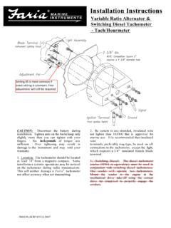
1 TAH-97029N (0258) page 1 of 5 Tachometer and Tach/Hourmeter Installation InstructionsSeries: ATS, ATHS, ATA, ATHA, ATHI TAH-97029 NRevised 08-07 Section 20(00-02-0258)Description These tachometers are indicators of engine revolutions per minute (RPM). Modelsequipped with hourmeter also record elapsed engine running driven models function from pulses generated by an alternator with 4, 8, 12,14, or 16 poles on the rotor. For magnetic sensor (pickup) driven models, the pulses areobtained from the ring gear of an engine s flywheel (having from 70 to 225 teeth) usingan electromagnetic sensor (pickup). Ignition signal driven models available for 4, 6 and 8 cylinder, spark ignited units are for negative ground, positive ground or isolated electrical systems.
2 If theinstrument is connected reverse polarity, it will not operate until proper connections aremade. All units are powered by 12 VDC. For 24 VDC applications, an optionalATVC12/24 converter must be used (see Fig. 3 or Fig. 5). Specifications Power Input: 12 VDC ( 16 V) [ to ].Backlight: 3 to Input Signal Voltage: Vrms minimum from a magnetic pickup or alternator (minimum 3-pole).Accuracy: Tachometer : 2% full : hours, 1 Range:-5 F to 185 F (-20 C to +85 C).Dial (Face Plate): 270 sweep with white numerals(over black background)Bezel: 304 Stainless : 0-3000 RPM and 0-4000 RPM (ATHA-40-12-A model only)Case Range:Measures elapsed time: 100,000 hours in Sensor Tachometer 3000 RPM; 70 - 225 pulses 12 VDCM odel #DesignationATS-30-12 Bright Stainless Steel BezelATS-30-12-ABlack Stainless Steel BezelATS-30-12-BSAE Bright Stainless Steel BezelATS-30-12-CSAE Black Stainless Steel BezelMagnetic Sensor Tach/Hourmeter 3000 RPM; 70 - 225 pulses 12 VDCATHS-30-12 Bright Stainless Steel BezelATHS-30-12-ABlack Stainless Steel BezelATHS-30-12-BSAE Bright Stainless Steel BezelATHS-30-12-CSAE Black Stainless Steel BezelAlternator Signal Tachometer 3000 RPM.
3 3 - 27 pulses 12 VDCATA-30-12 Bright Stainless Steel BezelATA-30-12-ABlack Stainless Steel BezelATA-30-12-BSAE Bright Stainless Steel BezelATA-30-12-CSAE Black Stainless Steel BezelAlternator Signal Tach/Hourmeter 4000 RPM; 3 - 27 pulses 12 VDCATHA-30-12 Bright Stainless Steel BezelATHA-30-12-ABlack Stainless Steel BezelATHA-30-12-BSAE Bright Stainless Steel BezelATHA-30-12-CSAE Black Stainless Steel BezelATHA-40-12-ABlack Stainless Steel BezelIgnition Signal Tach/Hourmeter 4000 RPM; 4, 6 or 8 cylinder 12 VDCATHI-40-12-ABlack Stainless Steel BezelOptional Items and Replacement BulbsATVC12/2424 VDC to 12 VDC Converter00-00-461712 VDC Light Bulb00-00-461824 VDC Light BulbGENERAL INFORMATIONP lease read the following Instructions before installing.
4 A visual inspection is recommended before Information and these Installation Instructions are intended for all Tachometer and Tachometer /Hourmeter these units in a place where they will be protected from rain and minimum distance of 12 in. (305 mm) from any coil, coil leads, or high volt-age wiring should be maintained. These units are intended for mounting in a flatpanel. Cut a 3-3/8 in. (86 mm) diameter hole as shown below. Remove the mountingbracket from the back of the unit. Insert the instrument from the front side of thepanel and replace the mounting bracket to secure the instrument in Mounting Instructions3-53/64 in.(97 mm)3-5/8 in.(92 mm)21/32 in.(17 mm)3-3/8 in. min.(86 mm)Mounting HoleRPMx 100 HOURS 110 WARNINGBEFORE BEGINNING Installation OF THIS MURPHY PRODUCT Disconnect all electrical power to the machine.
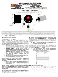
5 Make sure the machine cannot operate during Installation . Follow all safety warnings of the machine manufacturer. Read and follow all Installation ViewSideViewMounting BracketMounting HoleFor a selection of Magnetic Sensors (pickups) seeinstallation Instructions document (0258) page 2 of 5 CCAAUUTTIIOONN::Disconnect the battery/power source and determine voltage and polarity of the applicationbefore wiring the unit. Use the appropriate wire size. To wire the magnetic sensor pickup use 18 AWG ( mm2)twisted pair cable. Use insulated crimp-on (solderless) ring-type wire terminals. Allow a few inches of excesswire to make adjustments. Connecting or Replacing Light Bulb the light assembly socket one-eighth turn counterclockwise and removethe light assembly.
6 See Fig. 2 at replace the bulb, pull the bulb from the socket and replace with an 00-00-4617(for 12V), 00-00-4618 (for 24V) bulb or equivalent size as marked on the the lamp blade connector to (+) positive side of instrument lighting to Magnetic Sensor (see Fig. 2)The magnetic sensor (pickup) usually has two connections (terminals or wires) exit-ing from it. These connections are not polarized, either connection can be considered(+) positive or (-) negative signal. These two connections must be routed directly tothe unit. Do NOT ground one of the connections at the engine. one of the wires in the twisted pair (from magnetic sensor) to SIG . the other the wire in the twisted pair (from the magnetic sensor) to GND .Connecting to Power (see Fig.)
7 2)Important: These units are for 12 VDC a wire from BAT to a 12 VDC circuit activated by the ignition switch. a wire from GND to negative voltage source (electrical ground).Connecting ATVC12/24 Convertor (see Fig. 3)For 24 VDC applications, a ATVC12/24 convertor must be the ATVC12/24 convertor as shown in Fig. 3, at right. the ATVC12/24 convertor with a nut on the BAT and GND stud ter-minals of the that the stud terminal on the ATVC12/24 convertor becomes the BAT stud for connecting to 24 VDC. Proceed with the connection as shown. the 12 V bulb with the 24 V bulb supplied with the converter assembly. Mounting RequirementsATS and ATHS Series Models Typical WiringTO LIGHT (+) CIRCUITTO GROUND (-)TO UPLIGHTASSEMBLYCAUTION: TO 12 VDC ONLYSIGGNDBATSIGGNDBATTO GROUND (-)MOUNTINGBRACKETTO 24 VDC ATVC12 33 NNOOTTEE'BAT' STUDNUTLOCK WASHERFLAT WASHERNUTLOCK WASHERFLAT WASHER'GND' STUD'SIG' STUDDO NOT TIGHTEN THESENUTS AGAINST CLAMP(RECOMMENDED TORQUE:5 TO 7 INCH POUNDS)(RECOMMENDED TORQUE:5 TO 7 INCH POUNDS)CLAMPPANELWHEN USING ATVC12/2424-Volt convertor cardMake Sure Nuts AreLevel Under Card*2 PLACES ONLY**CAUTIOND evices containing solid state components can be damaged or caused tomalfunction when used in systems which incorporate inductive loads ( , solenoids, etc.
8 That can generate reverse voltage reduce the potential for this type of damage, install a properly sized fly-back or clamping diode across all inductive loads. Shown at right is a typical example:A typical diode is 1N4005 which is readily available from commercialsources. Failures of this type are not covered by our Limited 11 AATAH-97029N (0258) page 3 of 5 Typical Wiring For ATA And ATHA Series ModelsConnecting or Replacing Light Bulb the light assembly socket one-eight turn counterclockwise and remove the lightassembly . See Fig. 4 at replace the bulb, pull the bulb from the socket and replace with an 00-00-4617 (for12V), 00-00-4618 (for 24V) bulb or equivalent size as marked on the the lamp blade connector to (+) positive side of instrument lighting to Alternator (see Fig.)
9 4) a wire from SIG terminal an AC phase terminal (sometimes marked STA or R ) on your alternator. If your alternator does not have an AC phase terminal, sol-der the SIG wire to one of the negative or positive rectifier diodes of the soldering, securely tape the wire to an alternator lead or wiring harness to dampervibration on diode terminal. NOTE: On some alternators it may be necessary to removethe rear housing to solder the wire to the to Ignition (see Fig. 4) a wire from SIG terminal to the negative - side of the igniton coil or to theterminal marked TACH on solid-state ignition to Power (see Fig. 4)Important: These units are for 12 VDC a wire from BAT to a 12 VDC circuit activated by the ignition switch.
10 A wire from GND to negative voltage source (electrical ground).Connecting ATVC12/24 Convertor (see Fig. 5)For 24 VDC applications, a ATVC12/24 convertor must be the ATVC12/24 convertor as shown. the ATVC12/24 convertor with a nut on the BAT and GND stud terminals ofthe that the stud terminal on the ATVC12/24 convertor becomes the BAT stud forconnecting to 24 VDC. Proceed with the connection as shown. the 12 V bulb with the 24 V bulb supplied with the converter assembly. Calibration InstructionsCalibration for ATS and ATHS models The ATS and ATHS Series models have been designed to function with flywheelshaving anywhere from 70 to 225 teeth. This wide range is divided into 6 switchedpositions acting as a coarse adjustment as follows:SwitchPositionRangeofFlywheelTee th170 - 80 teeth281 - 100 teeth3101 - 130 teeth4131 - 160 teeth5161 - 190 teeth6191 - 225 the number of teeth on the flywheel is known, set the calibration courseadjustment switch , (see Fig.)