Transcription of TB-650 001 - Quick Start Front Panel Programming Features ...
1 Page 1 of 1 Copyright by Siemens VDO 2003 All rights reserved THIS IS A NON-CONTROLLED DOCUMENT To determine if Module is Front Panel Programmable, switch key to ON . The module will cycle through a self test and then display the software revision level. This is also indicated on the identification label located next to the harness connection. Techincal BulletinNo. TB-650 001 Product: Cluster Date Aug 03 Type: Electrical Description Quick Start Front Panel Programming Features For VDO Marine Instrument Module Issue 1 Software levels and greater are capable of being configured for the following functions using the MODE and ADJUST buttons.
2 Press MODE and ADJUST buttons and turn on power to module. Hold MODE and ADJUST buttons for five seconds until the display shows ProG . Release buttons. Press MODE button to select function. Press ADJUST to make changes. A=Tachometer: Adjustable from 1 12 pulses per revolution. Press and hold ADJUST button with up arrows to increase pulses per revolution, releasing button displays down arrows, Press and hold to decrease. Engines: IO 4cyl=2pulses, 6cyl=3pulses, 8cyl=4pulses OB All Mercury, OMC, Johnson, and Evinrude = 6 pulses Yamaha = 6 pulses, except on 70HP and lower = 3 pulses Suzuki = 6 pulses, except on 65HP and lower = 3 pulses Tohatsu/Nissan = 6 pulses, except on 70HP and lower = 2 pulses Honda = 2 pulses, except on 35HP 50HP = 3 pulses C=Trim: Press and hold ADJUST button with up arrows to increase number, releasing button displays " down arrows, press and hold to decrease.
3 Mercury IO = 0 Mercury OB = 1 OMC IO = 2 Volvo IO = 3 OMC OB = 4 Evinrude OB = 5 Johnson OB = 6 Honda OB = 7 Yamaha OB =8b=Speed: Adjustable from 50% to +50% Press and hold ADJUST button with up arrows to increase pulses per mile (reduce indicated speed), Releasing button displays down arrows. Press and hold ADJUST button to reduce pulses per mile (increases indicated speed). D= Fuel, E = Coolant temp, F = Oil Pressure Sensor = 1, VDO sensor = 0. Press ADJUST to Select Pressing both MODE and ADJUST buttons for 2 seconds will save changes. Releasing buttons will exit Programming mode and restart module. If no button is pressed for 20 seconds the program will automatically save any changes and exit.
4 Page 1 of 1 Copyright by Siemens VDO 2003 All rights reserved THIS IS A NON-CONTROLLED DOCUMENT Use the MODE button to Toggle through the 7 basic settings. Press both MODE and ADJUST to enter or change values. Arrow(s) show current function. Techincal 002 Product: Cluster Date Dec 2004 Type: Electric Description: Instrument Module Quick Start for Display Settings 1 Mode&SetMode&SetSET increasesDepth Alarmvalue. MODEto nextSET to set to MinutesSET to set MinutesSET to select 12 or24 Hour formatMODE to exitSET DecreasesDepth AlarmValue. MODETo nextSET to selectFeet or MetersMODETo nextSET to selectDepth ON orOFF.
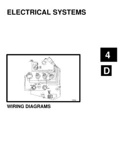
5 MODETo exitMode tonextClockDepth, Ft/MTotal DistanceTrip DistanceEngine HoursTrip HoursSeawater TempNote: Setting the Depth to Meterswill change the Distance Functionsto KM (Kilometers) andTemperature to - C (Centigrade)MODE & SET toreset Trip DistanceMODE & SET toreset Trip HoursPage 1 of 1 Copyright by Siemens VDO 2003 All rights reserved THIS IS A NON-CONTROLLED DOCUMENT Connector 12 11 10 9 8 7 6 5 4 3 2 1 24 23 22 21 20 19 18 17 16 15 14 13 (Harness side view) Electrical Pin out Pin No. Signal Pin No. Signal 1 Depth transducer signal 13 Depth transducer return 2 GND (depth) 14 Depth Shield 3 GND (signal) 15 Spare (TEST/PGM Signal Prototypes only) 4 GND (Power) 16 Seawater Temperature 5 Lighting Input 17 Check Engine Warning Switch (O/B only) 6 Trim Input 18 Oil Level Warning Switch (O/B only) 7 Serial TX 19 Mode Push-button 8 Serial RX 20 Adjust Push-button 9 Fuel Input 21 Speed sensor (+), 12v out 10 Oil Pressure Input (I/O) or, Oil Pressure Warning Switch (O/B) 22 Ignition (B+) 11 Engine Temperature Input (I/O) or, Engine Temp.
6 Warning Switch (O/B) 23 Battery 12 Tachometer Input 24 Speed Input The module connector is an Amp Mate-N-Lok. # 770587-1 The pin connectors are Amp # 770988-1 The extractor tool for removing the pins is Amp # 455822-2 Techincal 005 Product: Cluster Date Feb 2005 Type: Electric Description 1 Pin Connector and Troubleshooting GuidePage 2 of 2 Copyright by Siemens VDO 2003 All rights reserved THIS IS A NON-CONTROLLED DOCUMENT Page 1 of 1 Copyright by Siemens VDO 2003 All rights reserved THIS IS A NON-CONTROLLED DOCUMENT Techincal 006 Product: Cluster Date Feb 2005 Type: Electric Description.
7 Regal Speedometer Test 1 Page 1 of 1 Copyright by Siemens VDO 2003 All rights reserved THIS IS A NON-CONTROLLED DOCUMENT Techincal BulletinNo. TB-650 00 8 Product: Cluster Date Feb 2005 Type: Electrical Description Horn Capacitor Marine Cluster IO and OB Issue 1 VDO Marine Service Bulletin Product Line: All Outboard Clusters with Trim Date: Subject: Trim function on Honda and Yamaha There appears to be some confusion with regards to the wiring requirements for Honda and Yamaha outboards. Both Yamaha and Honda use a three wire trim sender that requires voltage input to operate. Pin # 6 Pin # 21 Ground Pin (3 or 4) Color Codes: Honda Yamaha Pin 6 Yellow/blue Pink Pin 21 or 12v Orange Orange Pin 3 or 4 Black Black (Ground) Trim Sensor Congratulations you have purchased one of the most advanced products in themarine industry today !
8 The VDO pitot pressure to speed pulse systemincorporates the following Features :o Generates speed pulses for boat speed below 5 miles per hour to over80 miles per houro Sensor fault detectiono Automatic Zero speed (sensor) calibrationo Automatic compensation for short interruptions of pitot pressureo Status indicator LED for system setup and diagnosticso Robust solid state pressure sensoro Very accurate and reliable microprocessor based designo Square wave speed pulse output to drive electronic speedometersVDO Pitot Pressure to Speed Pulse SystemOnly three connections are required to install the electronic are PowerGround and Speed pulse pictures and instructions on the next page willhelp you to install the electronic module outputs 10.
9 800 pulses per statutemile at a frequency of 3 Hertz per mile per value is the default calibration forthe VDO Boat Cluster. To use the module with other electronic speedometers set thespeedometer calibration to 10,800 pulses per Sheet # 0 521 000 004 Page 1 of 3 VDO MarineClusterElectronics ModulePressure SensorRed - PowerGreen - Pulses OutBlack - GroundPower Input and SpeedSensor Calibration for Zero SpeedManual Calibration ProcedureNote: This procedure is only done once at install. If the indicated speed is correct at low speed (10 mph) there is no needto do this The pressure sensor must be connected to Converter Module and Pitot Tube connected to sensor input The boat should be in the water with the Pitot Tube Remove the wire tie and sleeving from the white wire jumper exposing the contact pin as shown in picture A.
10 4. Insert the white wire contact pin into position 4 as shown in picture B . Mak e sure that the contact pin is fully While watching the RED LED on the module Turn the ignition switch to the on (NO T starting) The LED will blink 5 (once per second) times indicating good calibration. If not check the table on the next If okay, turn the ignition switch off and disconnect the white wire jumper. Replace the sleeving over thecontact pin and tie in place with a new wire tie (see picture C ). Note: The free end of the white jumper is connectedto ground so be sure to protect it against shorts to power or other A Picture B Picture C Pulse OutputConnections to VDO BoatClusterBlackRedGreenPin24 Pin21 Pin4 Instruction SheetPage 2 of 30 521 000 004 Instruction Sheet 0 521 000 004 Page 3 of 3 CalibrationJumper orSwitchInputInput Voltage FromSensorLED OperationOpenLess than 100mVLED off until the input voltage from the sensorreaches a value greater than 400mV.