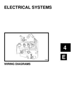
Transcription of ELECTRICAL SYSTEMS - boatfix.com
1 4D72938 ELECTRICAL SYSTEMSWIRING DIAGRAMS4D-0 - WIRING DIAGRAMS90-806535 893 Table of ContentsPageWiring Colors for MerCruiser4D-1.. Wire Color Abbreviations4D-1.. Wiring Diagrams4D-2.. MCM .. MCM V-6 Alpha Drive Engines4D-3.. MCM V-8 Alpha Drive Engines4D-4.. MCM V-8 Bravo Drive Engines4D-5.. MIE V-8 All Inboard and Ski Engines4D-6.. MCM Quicksilver Instrumentation4D-7.. MIE Quicksilver Instrumentation4D-8.. Dual Station Wiring (Using a Neutral SafetySwitch in Only one Remote Control)4D-9.. Dual Station Wiring (Using A Neutral SafetySwitch In both Remote Controls)4D-10.. Dual Station Wiring (Using a Neutral SafetySwitch in Engine Wiring Harness)4D-11.. Gauges4D-12.. Battery Meter Gauge4D-12.. Cruiselog4D-12.. Fuel Gauge and Sender4D-12.. Audio Warning System4D-13.. Water Temperature Gauge4D-13.. Oil Pressure Gauge4D-13.. Clock4D-13.. Wiring Diagrams for 502 EFI4D-15.
2 EFI Wiring Diagram4D-17.. ECM Component Connector Charts4D-21.. 4D - WIRING DIAGRAMSWIRING DIAGRAMS - 4D-190-806535940 893 Wiring Colors for MerCruiserBIA Color CodeWhere UsedBlackAll GroundsBrownReference Electrode-MerCathodeOrangeAnode Electrode-MerCathodeLt. Blue/WhiteTrim- Up SwitchGrayTachometer SignalGreen/WhiteTrim - Down SwitchTa nWater Temperature Sender to GaugeLt. BlueOil Pressure Sender to GaugePinkFuel Gauge Sender to GaugeBrown/WhiteTrim Sender to Trim GaugePurple/WhiteTrim- Trailer SwitchRedUnprotected Wires from BatteryRed/PurpleProtected (Fused) Wires from BatteryRed/PurpleProtected (+12V) to Trim PanelOrangeAlternator OutputPurple/YellowBallast BypassPurpleIgnition Switch (+12 V)Yellow/RedStarter Switch to Starter Solenoid to Neutral StartSwitchWire Color AbbreviationsBLKB lackBLUBlueBRNB rownGRYGrayGRNG reenORNO rangePNKPinkPURP urpleREDRedTANTa nWHTW hiteYELY ellowLITL ightDRKDark4D-2 - WIRING DIAGRAMS90-806535 893 Wiring DiagramsMCM.
3 Gray lead for use with service -Ignition System1 -Distributor2 -Shift Cutout Switch3 -Filter4 -Ignition CoilB -Starting System1 -Alternator2 -Electric Choke (2 BBL Only)3 -Ground Bolt4 -Starter5 -Circuit Breaker6 -Starter Slave SolenoidC-Audio Warning System1 -Water Temperature2 -Drive Unit Oil Level (If Equipped)3 -Oil Pressure SwitchD -Instrumentation System1 -Oil Pressure Sender2 -Water Temperature Sender3 -Trim SenderWIRING DIAGRAMS - 4D-390-806535940 893 MCM V-6 Alpha Drive Engines71877 WHT/REDWHT/GRNGRYPUR1234123456123123A -Ignition System1 -Distributor2 -Shift Cutout Switch3 -Terminal Block4 -Ignition CoilB -Starting System1 -Alternator2 -Electric Choke (2 BBL Only)3 -Ground Bolt4 -Starter5 -Circuit Breaker6 -Starter Slave Solenoid7 -Fuel PumpC-Audio Warning System1 -Water Temperature2 -Drive Unit Oil Level (If Equipped)3 -Oil Pressure SwitchD -Instrumentation System1 -Oil Pressure Sender2 -Water Temperature Sender3 -Trim Sender4D-4 - WIRING DIAGRAMS90-806535 893 MCM V-8 Alpha Drive Engines72935 WHT/REDWHT/GRNGRYPUR1234123123123456A -Ignition System1 -Distributor2 -Shift Cutout Switch3 -Terminal Block4 -Ignition CoilB -Starting System1 -Alternator2 -Electric Choke (2 BBL Only)3 -Ground Bolt4 -Starter5 -Circuit Breaker6 -Starter Slave SolenoidC-Audio Warning System1 -Water Temperature2 -Drive Unit Oil Level (If Equipped)
4 3 -Oil Pressure SwitchD -Instrumentation System1 -Oil Pressure Sender2 -Water Temperature Sender3 -Trim SenderWIRING DIAGRAMS - 4D-590-806535940 893 MCM V-8 Bravo Drive Engines72936 WHT/REDWHT/GRNGRYPUR1122435123123A -Ignition System1 -Distributor2 -Ignition CoilB-Starting and Charging Systems1 -Alternator2 -Ground Stud3 -Starter Motor4 -Circuit Breaker5 -Starter Slave SolenoidC -Audio Warning System1 -Water Temperature2 -Drive Unit Oil Level (If Equipped)3 -Oil Pressure SwitchD -Instrumentation System1 -Oil Pressure Sender2 -Trim Sender3 -Water Temperature Sender4D-6 - WIRING DIAGRAMS90-806535 893 MIE V-8 All Inboard and Ski Engines72937 WHT/REDWHT/GRNGRYPUR1212345621123 NOTE : Taped back brown and black wire may be used for an accessory. LOAD MUST NOT EXCEED 5 AMPSA-Ignition System1 -Distributor2 -Ignition CoilB -Starting and Charging System1 -Alternator2 -Ground Stud3 -Starer Motor4 -Circuit Breaker5 -Neutral Safety Switch6 -StarterSlave SolenoidC -Audio Warning System1 -Water Temperature2 -Transmission Fluid Temperture3 -Oil PressureD -Instrumention System1 -Oil Pressure Sender2 -Water Temperature SenderWIRING DIAGRAMS - 4D-790-806535940 893 MCM Quicksilver Instrumentation72938 BSI123456789 NOTE 1: Connect wires together with screw and hex nut.
5 Apply Quicksilver Liquid Neoprene to connection andslide rubber sleeve over 2: Power for a second fused accessory panel may be tasken from this connection. Load MUST NOT exceed35-40 amps. Panel ground wire MUST BE connected to instrument terminal that has an 8 gauge black (ground)harness wire connected to - Tachomter2 - Audio Warning Buzzer (if Equipped)3 - Oil Pressure4 - Water Temperature5 - Battery Meter6 - Ignition Switch7 - Trim Indicator8 - To 12 Volt Source (purple wire connection)9 - 20 Ampere Fuse4D-8 - WIRING DIAGRAMS90-806535 893 MIE Quicksilver Instrumentation72939 BSI13456287 NOTE 1: Connect wires together with screw and hex nut. Apply Quicksilver Liquid Neoprene to connection andslide rubber sleeve over 2: Power for a second fused accessory panel may be tasken from this connection. Load MUST NOT exceed35-40 amps. Panel ground wire MUST BE connected to instrument terminal that has an 8 gauge black (ground)harness wire connected to - Tachomter2 - Audio Warning Buzzer (if Equipped)3 - Oil Pressure4 - Water Temperature5 - Battery Meter6 - Ignition Switch7 - To 12 Volt Source (purple wire connection)8 - 20 Ampere FuseWIRING DIAGRAMS - 4D-990-806535940 893 Dual Station Wiring (Using a Neutral Safety Switch in Only one Remote Control)72940 BRN/WHTPURGRYBLKYEL/REDNOTE 3 PURPURGRYBLKBLKLT.
6 BLUBLKPURTANPURBLKRED/PURORNPURPURGRYBLK BLKPURLT. BLUBLKPURTANORNRED/PURPURBLKNOTE 2 NOTE 3 NOTE 1 YEL/REDYEL/REDNOTE 3 NOTE 3 BRN/WHTNOTE 1 YEL/REDYEL/REDYEL/REDBSISENDSENDSENDLTLT LTLTSW12V12V12V12 VGNDUNSWSIGGNDGNDGNDSENDSENDSENDLTLTLTLT SW12V12V12V12 VGNDUNSWSIGGNDGNDGND34512AB1234567 NOTE 1: Brown/white wire is taped back at instrument end. If installing on boat that is equipped with MerCruiser Stern Drive, brown/whitewire is connected to trim sender terminal block. If installing on MerCruiser Inboard, brown/white wire is taped back at engine end, or it maybe used for an accessory (limit 5 amperes)NOTE 2 : An accessory fuse panel may be connected at this location. The combined current draw of the primary station and secondarystation MUST NOT exceed 35 3 : Connect wires together with screw and hex nut. Apply Quicksilver Liquid Neoprene to connection and slide rubber sleeve - Secondary Station1 - Stop -Start Panel2 - Tachometer3 - Oil Pressure4 - Water Temperature5 - Battery MeterB - Primary Station1 - Ignition Switch2 - Tachometer3 - Oil Pressure4 - Water Temperature5 - Battery Meter6 - To Engine7 - 20 Ampere Fuse4D-10 - WIRING DIAGRAMS90-806535 893 Dual Station Wiring (Using A Neutral Safety Switch In both Remote Controls)72941 BRN/WHTPURGRYBLKYEL/REDNOTE 3 PURPURGRYBLKBLKLT.
7 BLUBLKPURTANPURBLKRED/PURORNPURPURGRYBLK BLKPURLT. BLUBLKPURTANORNRED/PURPURBLKNOTE 2 NOTE 3 NOTE 1 YEL/REDYEL/REDNOTE 3 BRN/WHTNOTE 1 YEL/REDYEL/REDYEL/REDNOTE 3 NOTE 3 YEL/REDSENDSENDSENDLTLTLTLTSW12V12V12V12 VGNDUNSWSIGGNDGNDGNDBSISENDSENDSENDLTLTL TLTSW12V12V12V12 VGNDUNSWSIGGNDGNDGND345121234576 YEL/REDABNOTE 1: Brown/white wire is taped back at instrument end. If installing on boat that is equipped with MerCruiser Stern Drive, brown/whitewire is connected to trim sender terminal block. If installing on MerCruiser Inboard, brown/white wire is taped back at engine end, or it maybe used for an accessory (limit 5 amperes)NOTE 2 : An accessory fuse panel may be connected at this location. The combined current draw of the primary station and secondarystation MUST NOT exceed 35 3 : Connect wires together with screw and hex nut. Apply Quicksilver Liquid Neoprene to connection and slide rubber sleeve - Secondary Station1 - Stop -Start Panel2 - Tachometer3 - Oil Pressure4 - Water Temperature5 - Battery MeterB - Primary Station1 - Ignition Switch2 - Tachometer3 - Oil Pressure4 - Water Temperature5 - Battery Meter6 - To Engine7 - 20 Ampere FuseWIRING DIAGRAMS - 4D-1190-806535940 893 Dual Station Wiring (Using a Neutral Safety Switch in Engine Wiring Harness)72942 BRN/WHTPURGRYBLKYEL/REDNOTE 3 PURPURGRYBLKBLKLT.
8 BLUBLKPURTANPURBLKRED/PURORNPURPURGRYBLK BLKPURLT. BLUBLKPURTANORNRED/PURPURBLKNOTE 2 NOTE 3 NOTE 1 YEL/REDYEL/REDNOTE 3 NOTE 3 BRN/WHTNOTE 1 YEL/REDYEL/REDSENDSENDSENDLTLTLTLTSW12V1 2V12V12 VGNDUNSWSIGGNDGNDGNDBSISENDSENDSENDLTLTL TLTSW12V12V12V12 VGNDUNSWSIGGNDGNDGND345121234576 ABNOTE 1: Brown/white wire is taped back at instrument end. If installing on boat that is equipped with MerCruiser Stern Drive, brown/whitewire is connected to trim sender terminal block. If installing on MerCruiser Inboard, brown/white wire is taped back at engine end, or it maybe used for an accessory (limit 5 amperes)NOTE 2 : An accessory fuse panel may be connected at this location. The combined current draw of the primary station and secondarystation MUST NOT exceed 35 3 : Connect wires together with screw and hex nut. Apply Quicksilver Liquid Neoprene to connection and slide rubber sleeve - Secondary Station1 - Stop -Start Panel2 - Tachometer3 - Oil Pressure4 - Water Temperature5 - Battery MeterB - Primary Station1 - Ignition Switch2 - Tachometer3 - Oil Pressure4 - Water Temperature5 - Battery Meter6 - To Engine7 - 20 Ampere Fuse4D-12 - WIRING DIAGRAMS90-806535 893 GaugesBattery MeterGauge72814a - Lamp Mounting Holeb - Purple (or White) Jumper Wire from This Terminal to I.
9 (or+) Terminal on Water Temperature or Oil Pressure .. Gaugec - Black Jumper Wire from This Terminal to Ground Terminal on Water Temperature or Oil Pressure GaugebcaCruiselog72815baa - Connect to Ignition Switch 12 VoltPositive(+) Source (PURPLE WIRE)b - Connect to Negative ( ) Ground (BLACK WIRE)Fuel Gauge andSender72816 BLKBLKPNK1234 Note 1 Note 2 PNKNote 1: Connect terminal to Ignition or Accessory Terminal of 2: Connect to Negative Battery Terminal or Suitable - Tank Sender2 - Sender Capsule3 Fuel Gauge (Black Case)WIRING DIAGRAMS - 4D-1390-806535940 893 Audio Warning System!WARNINGB uzzer is not external ignition-proof; therefore,DO NOT mount buzzer in engine or fuel - Audio Warning Buzzer2 - Water Temperature Switch3 - Oil Pressure Switch4 - 12 Volt Power SourceWater Temperature Gauge728192311 - Ground (BLack)2 - Switched 12 Volt Terminal (PURPLE)3 - Sender Lead (TAN)Oil Pressure Gauge728191231 - Ground (Black)2 - Switched 12 Volt Terminal (PURPLE)3 - Sender Lead (LIGHT BLUE)Clock728181231 - Connect Wire (DARK BLUE)to an Ignition Terminal of anAdjacent Gauge or to Any Switched 12 Volt - Connect to Instrument Harness (RED/PURPLE) Lead and Slide a Rubber Sleeve over the - Connect Wire (BLACK) to a Terminal on an Adjacent Gaugeor to Another Suitable - WIRING DIAGRAMS90-806535 893 Quicksilver Instrumentation For 454 Magnum EFI Ski123486758 NOTE 1: Connect wires together with screw and hex nut.
10 Apply Quicksilver Liquid Neoprene to connection andslide rubber sleeve over 2: Power for a second fused accessory panel may be tasken from this connection. Load MUST NOT exceed35-40 amps. Panel ground wire MUST BE connected to instrument terminal that has an 8 gauge black (ground)harness wire connected to - Tachomter2 - Audio Warning Buzzer (if Equipped)3 - Oil Pressure4 - Water Temperature5 - Battery Meter6 - Ignition Switch7 - To 12 Volt Source (purple wire connection)8 - 20 Ampere FuseWIRING DIAGRAMS - 4D-1590-806535940 893 Wiring Diagrams for 502 EFI716931234512312 CABbcaA-Audio Warning System1 - Oil Pressure Switch2 - Drive Unit Oil LevelB - Instrumentation System1 - Oil Pressure Sender2 - Water Temperature Sender3 - Trim SenderC - Charging and Starting System1 - Alternator 2 - Ground Stud3 - Starter4 - Circuit Breaker5 - Starter Slave Solinoida - Positive Power Wire To EFI System Harnessb - Harness Connector To EFI System Harnessc - Auxiliary Tachometer Lead4D-16 - WIRING DIAGRAMS90-806535 893 Wiring Diagrams (Continued)