Transcription of TDA7377 - e-ele.net
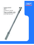
1 TDA7377 . 2 x 30W DUAL/QUAD POWER AMPLIFIER FOR CAR RADIO. HIGH OUTPUT POWER CAPABILITY: 2 x 35W . 2 x 30W/4 EIAJ. 2 x 30W/4 EIAJ. 2 x 20W/4 1 KHz, 10%. 4 x 6W/4 1 KHz, 10%. 4 x 10W/2 1 KHz, 10% MULTIWATT15V MULTIWATT15H. MINIMUM EXTERNAL COMPONENTS ORDERING NUMBERS: COUNT: TDA7377V TDA7377H. NO BOOTSTRAP CAPACITORS. NO BOUCHEROT CELLS. INTERNALLY FIXED GAIN (26dB BTL) TO GND. ST-BY FUNCTION (CMOS COMPATIBLE) TO VS. NOAUDIBLE POPDURING ST-BYOPERATIONS ACROSS THE LOAD. DIAGNOSTICS FACILITY FOR: SOFT SHORT AT TURN-ON. CLIPPING OVERRATING CHIP TEMPERATURE WITH. OUT TO GND SHORT SOFT THERMAL LIMITER.
2 OUT TO VS SHORT LOAD DUMP VOLTAGE SURGE. SOFT SHORT AT TURN-ON VERY INDUCTIVE LOADS. THERMAL SHUTDOWN PROXIMITY FORTUITOUS OPEN GND. Protections: REVERSED BATTERY. OUPUT AC/DC SHORT CIRCUIT ESD. BLOCK DIAGRAM. DIAGNOSTICS. September 1998 1/10. TDA7377 . DESCRIPTION tees the highest possible power performances with extremely reduced component count. The The TDA7377 is a new technology class AB car on-board clip detector simplifies gain compression radio amplifier able to work either in DUAL operation. The fault diagnostics makes it possible BRIDGE or QUAD SINGLE ENDED configuration.
3 To detect mistakes during car radio set assembly The exclusive fully complementary structure of the and wiring in the car. output stage and the internally fixed gain guaran- GENERAL STRUCTURE. ABSOLUTE MAXIMUM RATINGS. Symbol Parameter Value Unit Vop Operating Supply Voltage 18 V. VS DC Supply Voltage 28 V. Vpeak Peak Supply Voltage (for t = 50ms) 50 V. IO Output Peak Current (not repetitive t = 100 s) A. IO Output Peak Current (repetitive f > 10Hz) A. Ptot Power Dissipation (Tcase = 85 C) 36 W. Tstg, Tj Storage and Junction Temperature -40 to 150 C. THERMAL DATA. Symbol Description Value Unit Rth j-case Thermal Resistance Junction-case Max C/W.
4 PIN CONNECTION (Top view). DIAGNOSTICS. 2/10. TDA7377 . ELECTRICAL CHARACTERISTICS (Refer to the test circuit, VS = ; RL = 4 ; f = 1 KHz;. T amb = 25 C, unless otherwise specified Symbol Parameter Test Condition Min. Typ. Max. Unit VS Supply Voltage Range 8 18 V. Id Total Quiescent Drain Current RL = 150 mA. VOS Output Offset Voltage 150 mV. PO Output Power THD = 10%; RL = 4 . Bridge 18 20 W. Single Ended 6 W. Single Ended, RL = 2 10 W. PO max Max. Output Power (**) VS = , Bridge 31 35 W. PO EIAJ EIAJ Output Power (**) VS = , Bridge 27 30 W. THD Distortion R L = 4 . Single Ended, PO = to 4W %.)
5 Bridge, PO = to 10W %. CT Cross Talk f = 1 KHz Single Ended 70 dB. f = 10 KHz Single Ended 60 dB. f = 1 KHz Bridge 55 dB. f = 10 KHz Bridge 60 dB. R IN Input Impedance Single Ended 20 30 K . Bridge 10 15 K . GV Voltage Gain Single Ended 19 20 21 dB. Bridge 25 26 27 dB. GV Voltage Gain Match dB. EIN Input Noise Voltage R g = 0; A weighted, Non Inverting Channels 2 V. Inverting Channels 5 V. Bridge Rg = 0; 22Hz to 22 KHz V. SVR Supply Voltage Rejection R g = 0; f = 300Hz 50 dB. A SB Stand-by Attenuation PO = 1W 80 90 dB. ISB ST-BY Current Consumption VST-BY = 0 to 100 A.
6 V SB ST-BY In Threshold Voltage V. V SB ST-BY Out Threshold Voltage V. Ipin7 ST-BY Pin Current Play Mode V pin7 = 5V 50 A. Max Driving Current Under 5 mA. Fault (*). Icd off Clipping Detector d = 1% (**) 90 A. Output Average Current Icd on Clipping Detector d = 5% (**) 160 A. Output Average Current Vsat pin10 Voltage Saturation on pin 10 Sink Current at Pin 10 = 1mA V. (*) See built-in S/C protection description (**) Pin 10 Pulled-up to 5V with 10K ; RL = 4 . (**) Saturated square wave output. 3/10. TDA7377 . STANDARD TEST AND APPLICATION CIRCUIT. Figure 1: Quad Stereo 10K R1.
7 ST-BY VS. C7 C6 C5. 10 F 100nF 1000 F. 7 13 3. IN FL 4 1. C1 F C10 2200 F OUT FL. IN FR 5. 2. C2 F. C9 2200 F OUT FR. IN RL 12. C4 F 15. IN RR 11 C11 2200 F OUT RL. Note: C3 F. C9, C10, C11, C12 could be 14. 6. reduced if the 2 operation is not 8 9 10 C12 2200 F OUT RR. required. C8 47 F. DIAGNOSTICS. D94AU063A. Figure 2: Double Bridge 10K R1. ST-BY VS. C5 C4 C3. 10 F 100nF 1000 F. 7 13 3. IN L 4 1. C1 F 5 OUT L. 2. IN R 12. 15. C2 F 11. OUT R. 6 14. C8 47 F 8 9 10. DIAGNOSTICS. D94AU064A. Figure 3: Stereo/Bridge 10K. ST-BY VS. 10 F 100nF 1000 F. 7 13 3. IN L 4 1. OUT L.
8 F 2200 F. IN L 5 2. OUT R. F 2200 F. IN BRIDGE 12 15. F 11 OUT. BRIDGE. 6 14. 8 9 10. 47 F. DIAGNOSTICS. D94AU065A. 4/10. TDA7377 . High Application Flexibility The fully complementary output stage was made The availability of 4 independent channels makes possible by the development of a new compo- it possible to accomplish several kinds of applica- nent: the ST exclusive power ICV PNP. tions ranging from 4 speakers stereo (F/R) to 2 A novel design based upon the connection shown speakers bridge solutions. in fig. 20 has then allowed the full exploitation of In case of working in single ended conditions the its possibilities.
9 Polarity of the speakers driven by the inverting The clear advantages this new approach has over amplifier must be reversed respect to those driven classical output stages are as follows: by non inverting channels. This is to avoid phase inconveniences causing sound alterations especially during the reproduc- tion of low frequencies. Rail-to-Rail Output Voltage Swing With No Need of Bootstrap Capacitors. Easy Single Ended to Bridge Transition The output swing is limited only by the VCEsat of the output transistors, which is in the range The change from single ended to bridge configu- of (Rsat) each.
10 Rations is made simply by means of a short circuit Classical solutions adopting composite PNP- across the inputs, that is no need of further exter- NPN for the upper output stage have higher nal components. saturation loss on the top side of the waveform. This unbalanced saturation causes a signifi- Gain Internally Fixed to 20dB in Single Ended, cant power reduction. The only way to recover 26dB in Bridge power consists of the addition of expensive Advantages of this design choice are in terms of: bootstrap capacitors. components and space saving Absolute Stability Without Any External output noise, supply voltage rejection and dis- Compensation.
