Transcription of TECHNICAL DATA SHEET ISSUED BY TIMBER …
1 TIMBER QUEENSLAND LIMITED TECHNICAL DATA SHEET 18 TIMBER FLOORS recommended installation Revised March 2014 Page 1 This information SHEET outlines the recommended practices for laying TIMBER strip floors over TIMBER and engineered TIMBER joists (it does not include steel joists), structural sub-floors such as plywood, particleboard and over concrete, but does not include direct adhesive fix to slabs. When laying a TIMBER strip floor over joists, either directly on the joists or on SHEET flooring fixed to joists, adequate sub- floor ventilation is essential for the satisfactory performance of the floor . Sub- floor ventilation recommendations are therefore included in this data SHEET . SUB- floor VENTILATIONWhen the lower surface of TIMBER floors or structural sub-floors (over which a TIMBER floor is laid) are exposed to the ground and the space is enclosed (by brickwork etc.), the sub- floor space must be adequately ventilated with permanent vents installed in the masonry during construction.
2 The humidity in an enclosed sub- floor space can have a profound effect on the performance of a floor . If conditions are very moist, the lower surface of the boards may take up moisture, causing substantial swelling. Differential movement between the upper and lower surfaces of floor boards may also cause boards to cup. Similarly, caution needs to be exercised with TIMBER floors laid in areas where the microclimate is often moist. In such locations the floor may reach higher moisture contents than in other nearby areas and additional allowance for expansion of the floor may be required (Refer Data SHEET 2 - Pre- installation Requirements). TIMBER floors should not be laid over moist sub- floor spaces, and structural sub-floors ( plywood) cannot be relied upon to prevent moisture uptake in the T&G flooring if humidities in the sub- floor space remain high for extended requirementsT&G floors should be provided with sub- floor ventilation that exceeds minimum Building Code of Australia (BCA) requirements.
3 The levels outlined in the BCA (currently limited to 6000 mm per meter length of wall for higher humidity areas) are primarily to limit the moisture content of sub- floor framing timbers, which can generally tolerate greater fluctuations in moisture content, than TIMBER floors. The recommended minimum ventilation for T&G TIMBER floors is 7500 mm2 per meter length of wall, with vents evenly spaced to ensure that cross ventilation is provided to all sub- floor areas (refer to the following figure). In some localities, to meet constraints associated with energy efficiency, it may be decided to reduce ventilation levels to the values provided in the BCA. The BCA also outlines that a moisture barrier over the soil beneath the building reduces ventilation requirements and this approach is equally applicable to TIMBER floors. If ventilation below the recommended level is used, due consideration should be given to alternative measures as outlined above and particular attention should be paid to ensuring that the sub- floor space remains dry throughout all seasons.
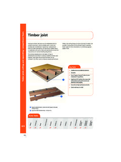
4 The type of vent may also need to be considered with buildings in bushfire areas which limits the mesh size used in vents. Some commercially available vents of various types, their dimensions, net ventilation area and required spacing is provided below for coastal Zone 3. BCA relative humidity zones and associated BCA ventilation requirements are also provided below. It should be noted that the maximum vent spacing irrespective of net ventilation area is 2m and that any screens that may be necessary in bushfire areas or for vermin proofing may restrict airflow and this may need to be compensated for. Vents evenly located around the perimeter and within 600 mm of cornersVents sized and spaced to provide 7500 mm2 of opening per meter length of wall400 mmminimum elsewhere150 mm minimum up to 2 m from wallA DRY SUB- floor IS ESSENTIALFall from buildingFigure 1 - Sub- floor VentilationVentilation efficiency and site drainageThe sub- floor space must be free from all building debris and vegetation.
5 Obstacles that prevent air-flow to and from vents will reduce the efficiency of the sub- floor ventilation system. Landscaping should not limit airflow around the external perimeter of the sub- floor space, and structural elements should not limit airflow. Vents should be installed in the masonry course below floor bearers, and should not be obscured by engaged piers or piers/stumps/columns which support the floor structure, or by any services present. Where external structures (fences etc.) or landscape may reduce airflow, recommended PRACTICE // MARCH 2014 TIMBER FLOORS RECOMMENDEDINSTALLATION PRACTICESTECHNICAL DATA SHEETISSUED BY TIMBER QUEENSLAND18 TIMBER QUEENSLAND LIMITED TECHNICAL DATA SHEET 18 TIMBER FLOORS recommended installation Revised March 2014 Page 2consideration should be given to the use of more than the minimum number of verandahs or decks are constructed outside the dwelling perimeter, care should be taken to ensure that the amount of ventilation provided around the verandah or deck perimeter is equivalent to or greater than the amount required for the adjacent external wall.
6 Where ventilation is obstructed by patios etc., additional ventilation should be provided to ensure that the overall level of ventilation is maintained and cross flow is adequate natural ventilation cannot be provided to sub- floor spaces, a mechanical ventilation system should be installed which replaces all of the air in this space on a regular basis, and prevents the formation of dead air there are doubts over the sub- floor humidity (areas of high water table, reduced airflow due to minimum clearances between the sub- floor framing and ground, external structures etc.), again, a polyethylene membrane laid over the soil should be considered (taped at joints and fixed to stumps and walls). As discussed above, this can significantly reduce moisture uptake by the sub- floor air. Increased levels of ventilation should also be considered in such instances.
7 With dwellings on sloping blocks that have enclosed sub- floor spaces, the possibility of seepage should be taken into consideration and appropriate control measures taken prior to the installation of the drainage system provided to the dwelling site should ensure that run-off water will drain away from the building perimeter (not towards it) and that run-off water is prevented from entering the sub- floor space. The ground beneath a suspended floor should also be graded so that no ponding is possible. Where springs or aquifers are present ( exposed by earthworks on sloping sites) and cause water to enter the sub- floor space, a closed drainage system should be installed under the dwelling to remove this water. The ventilation system will not cope with this level of moisture in the sub- floor FIXING REQUIREMENTSDue to climatic differences occurring between and throughout each state, the fixing requirements of the floor need to be carefully assessed.
8 Due to this, applicable fixing requirements differ to some degree between states and between locations within each (face) nailing is a more robust fixing method than say floors secretly fixed with beads of adhesive. Top (face) nailed floors can therefore accommodate greater movement and expansion pressure without buckling. Increasing the amount of adhesive used will also provide a more robust fixing and some installers elect to bond the floor with a full bed of adhesive. Where greater floor expansion is expected after installation the method of fixing chosen and associated spacing of fixings or amount of adhesive used requires consideration. A full bed of adhesive in humid localities will limit floor expansion but can also contribute to higher pressure at board edges making the floor more prone to peaking, resulting in a cupped appearance and at times tenting of should also be noted that the specified recommendations contained in this manual are generic in nature and although frequently used, installers with knowledge and experience in a particular locality may fix a floor in a manner that differs from that outlined here.
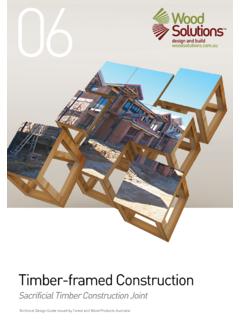
9 There are also an increasing number of flooring manufacturers who are producing specific products with accompanying installation instructions and such instructions should be strictly followed. This includes wider thin overlay boards and standard profile flooring for secret fixing. Other manufacturers recommend that standard profile flooring should not be secretly fixed. It should be recognised that specific manufacturing methods may apply to certain products and other similar looking products of different manufacture may not perform equivalently even with the same fixing method. The installation methods covered by this manual are used extensively by many installers throughout Australia and form the basis for the industry s FOR EXPANSION IN FLOORSF itted floors require a minimum 10 mm expansion gap between the floor boards and any internal or external wall structures.
10 However, where board ends abut doorways, the gap may be reduced to a neat fit but with a small gap (approximately 1 mm) to prevent rubbing. Floors up to 6 m wide (measured at right angles to the run of boards) should not require intermediate expansion joints provided that it is a normal in-service environment. For floor widths over 6 m or where extra allowance for expansion is required ( moist locations), cramping pressure needs to be considered along with providing an mm gap every 800 mmAluminium joineryAluminium angleCork intermediate expansion joint10 mm min gap10 mm min gap10 mm min gapNog under expansion joint and fix to one side of boardRemove tongues from boardsBrass cap fixed to noggingBullnose mouldingFigure 2 - Expansion gap details TIMBER QUEENSLAND LIMITED TECHNICAL DATA SHEET 18 TIMBER FLOORS recommended installation Revised March 2014 Page 3intermediate expansion joint, or a series of smaller expansion gaps every 800 mm to 1000 mm to provide equivalent spacing.