Transcription of Technical Document Seismic Technical Guide
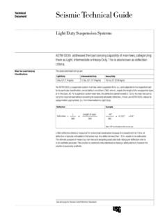
1 Seismic Technical GuideTechnicalDocument Hanger Wire AttachmentCode Requirements1 The International Building Code (IBC) defines the requirement for hanger wire and their supports and attachment methods. However, there are exceptions and the application of hanger wires in a Seismic design category can meet code requirements in different recommends that the design team, consulting engineers and code officials work together to analyze these factors and determine the appropriate construction and application of hanger wire attachment. Because codes continue to evolve, check with local officials prior to designing and installing a suspension 12-gauge, galvanized, soft-annealed steel wire Manufactured in accordance with ASTM A641 Meets or Exceeds Federal Specification QQ-W-461H Note: 12-gauge hanger wire produced by USG meets these Data12-Gauge WireWire Tie Failure / Pullout LoadTypical 3 wrap tie1270 3 wrap tie358 load+550 Strength (Ksi)80 Per ASTM C636 Note.
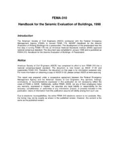
2 Tight wrap typically consists of three complete wraps within 1 in. Some jurisdictions may require four complete wraps for bracing wires. These requirements may vary by Options Hanger wire splices are typical when the ceiling drop is greater than the length of the wire available and are allowed in Seismic ceiling construction. The industry standard is to loop and tie the wire ends with three tight turns, or use a square knot. The square knot is the stronger of the two options at 550 lbs. versus 350 lbs. for the loop and tie Wire SpliceWire Tie FailureLoop and Tie350 Knot550 lbs. Note: Accessories by others for securing hanger wire splices should be evaluated for pullout and strength.
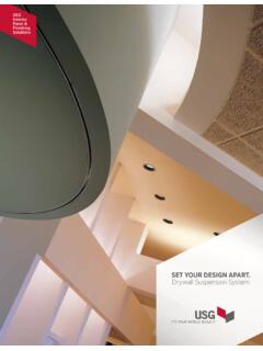
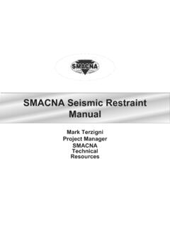
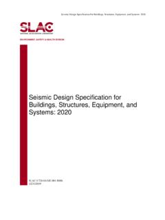
3 1 See last page for Seismic Code Reference Standards2 Hanger Wire AttachmentApplication Hanger Wire Splices Loop and Tie ApplicationStep 1 Connect the hanger wire ends together through two 2 Wrap the hanger wire ends securely around itself with three complete turns within 1 in. Square Knot ApplicationStep 1 Create an approximate 5 in. bend in the end of each hanger wireStep 2 With the short ends opposed, bring the right-hand end over the left-hand and loop the short end under and around the left-hand end, as 3 Loop the left-hand short end back up and around the right-hand loop, with the left-hand end over the right-hand end and bring the left-hand end under the loop of the right-hand end, as 4 Draw the knot tight.
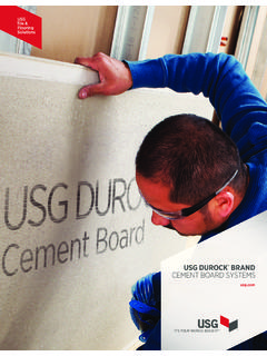
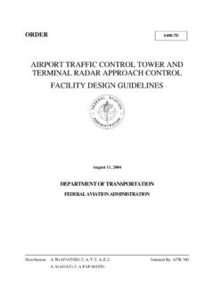
4 Step 5 Wrap the hanger wire ends securely around itself with three complete turns within 1 : In the symmetry of the knot, the wire piece on the left emerges parallel from below the other loop, while the wire piece on the right emerges parallel from above the other loop. This appearance confirms you have tied the square knot correctly. Hanger Wire Attachment 3 Application Attachment to TeeInsert the hanger wire ends through a wire hole in the tee and wrap the wire end securely around itself with three complete turns within 3 in. Ensure the remaining wire end is secured so that it does not interfere with the place-ment of ceiling Donn main tees are produced with round hanger wire holes in the tee web at regular intervals.
5 There are also rectangular (convenience) holes located in the tee bulb at regular intervals. The typical location for the hanger and bracing (splay) wires is in the round holes, but the rectangular (convenience) holes may also be used when needed. We have load tested the rectangular (convenience) holes located in the tee bulb with 12 ga. hanger wire on a 45 angle. The failure load is in excess of 400 lbs. This far exceeds the 250 lb. minimum prescribed by the code for the connections of the bracing (splay) : USG has qualified the use of the rectangular (convenience) holes located in the tee bulb through comparison testing by Seismic shake-table analysis.
6 In these tests the rectangular (convenience) holes located in the tee bulb were used for all hanger wire attachments to the tee. Round Hanger Wire Hole Attachment Rectangular (Convenience) Hole Attachment Alternative Hanger Wire Spacing ASTM C635 addresses the load carrying capability of main tees, categorizing them as Light, Intermediate or Heavy Duty. This is also known as deflection criteria. The associated load ratings are: Light Duty Intermediate Duty Heavy Duty 5 ( kg/m) 12 ( kg/m) 16 ( kg/m)Hanger wires are typically spaced 4 ft.
7 Along the main tee. Reducing the hanger wire spacing on Intermediate Duty main tees from 4 ft. to 3 ft. can achieve Heavy Duty load carrying capacity values. Notes: Reducing the hanger wire spacing on Intermediate Duty main tees can achieve Heavy Duty load carrying capacity values but does not change the duty classification of the main tee. The performance of Donn suspension systems is based on the specific combination of superior components, and the design and installation methods shown. Components from other manufacturers were not evaluated, and their use or any mixed use is not recommended.
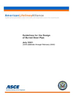
8 Many jurisdictions accept the installation of Intermediate Duty main tees with additional supports to achieve Heavy Duty load carrying capacity values, however, some jurisdictions will not accept this application. Check with a local official prior to designing and installing a suspended ceiling wireround hanger wire holeRound Hanger Wire Hole Attachment rectangular convenience holehanger wireRectangular (Convenience) Hole Attachment 3 ceilingstructuremain tee4 Hanger Wire AttachmentApplication AnchorageThe International Building Code (IBC), through references to ASCE/SEI 7 Minimum design Loads for Buildings and Other Structures, American Society of Civil Engineers/Structural Engineering Institute (ASCE/SEI)
9 , defines the requirements for component anchorage. The requirements are as follows: Component attachments shall be bolted, welded, or otherwise positively fastened without consideration of frictional resistance produced by the effects of gravity. A continuous load path of sufficient strength and stiffness between the component and the supporting structure shall be provided. Local elements of the structure including connections shall be designed and constructed for the component forces where they control the design of the elements or their in Concrete or Masonry Anchors in concrete shall be designed in accordance with Appendix D of ACI 318.
10 Anchors in masonry shall be designed in accordance with ACI 530. Anchors shall be designed to be governed by the tensile or shear strength of a ductile steel element. Exception: Anchors shall be permitted to be designed so that the attachment that the anchor is connecting to the structure undergoes ductile yielding at a load level corresponding to anchor forces not greater than their design strength, or the minimum design strength of the anchors shall be at least times the factored forces transmitted by the Anchors Post-installed anchors in concrete shall be pre-qualified for Seismic applications in accordance with ACI Concrete and Masonry or other approved qualification procedures.