Transcription of Technical Explanation for Basic Switches - Omron
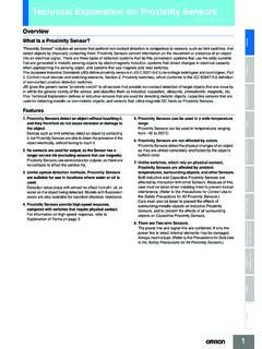
1 Technical Explanation for Basic Switches CSM_MicroSwitch_TG_E_3_2. Introduction What Is a Basic switch ? Sensors A Basic switch is a small switch with a very small contact gap and snap-action mechanism and with a contact structure that Switches for a specified movement and specified force enclosed in a case with an actuator provided on the exterior of the case. The following Basic switch structure is shown as an example. Basic Switches are mainly comprised of five components. Switches Actuator Contact section Transfers external move- Securely opens and ment and force to the in- closes the electrical circuit. Safety Components ternal mechanism.
2 Case Relays Protects the internal mechanism with superior electrical insulation and mechanical strength. Control Components Snap-action mechanism Terminal section Performs a snap action us- Connects to external cir- ing a superior conductive cuits. spring. Structural Diagram of Typical Basic switch Automation Systems Motion / Drives Energy Conservation Support /. Environment Measure Equipment Power Supplies /. In Addition Others Common 1. Technical Explanation for Basic Switches Explanation of Terms General Terms (1) General Terms (3) Terms Related to Durability Sensors Basic switch : A small-size switch with a very small contact gap and Mechanical Durability: The switching durability when a switch is snap-action mechanism and with a contact structure that Switches by operated at a specified frequency and specified overtravel (OT).
3 A specified movement and specified force enclosed in a case with an without the contacts energized. actuator provided on the exterior of the case. ( Basic Switches are Electrical Durability: The switching durability when a switch is often referred to as merely " Switches " in this catalog.) operated at a specified frequency and specified overtravel (OT) under switch with Contacts: A type of switch that achieves the switching the rated load. Switches function through the mechanical switching of contacts. Use as opposed to a semiconductor switch with switch characteristics. (4) Standard Test Conditions Contact Form: The structure of the electrical I/O circuits of contacts Switches are tested under the following conditions.
4 Used according to the type of application. (Refer to Contact Form Ambient temperature: 20 2 C. table later in this section.) Relative humidity: 65 5%RH. Safety Components Ratings: Value generally used as a reference for ensuring the Atmospheric pressure: kPa characteristics and performance of Switches , such as the rated current and rated voltage. Ratings are given assuming specific (5) N-level Reference Value conditions (such as the type of load, current, voltage, and frequency). The N-level reference value indicates the failure rate of the switch . Resin Filled (Molded Terminal): A terminal which is filled with resin The following formula indicates that the failure rate is 1/2,000,000 at after being connected to the internal circuit of the switch with a lead to a reliability level of 60% ( 60).
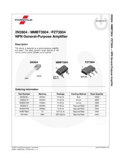
5 Eliminate exposed current-carrying metal parts and thereby to 60 = 10 6/operations enhance the drip-proof properties of the switch . Relays Insulation Resistance: The resistance between discontinuous (6) Contact Shape and Type terminals, between terminals and non-current-carrying metal parts, Main Processing Main and between terminals and ground. Shape Type material method application Dielectric Strength: The threshold value up to which insulation will Crossbar contacts are used for not be destroyed when a high voltage is applied for 1 minute to a ensuring high contact reliability for Control Components predetermined measurement location.
6 Switching micro loads. Gold The moving contact and fixed contact Contact Resistance: The electrical resistance of the contact point of come in contact with each other at a right Crossbar alloy contacts. Generally, the contact resistance includes the conductive contact Silver angle. Crossbar contacts are made with materials that environment-resistant, resistance of the spring or terminal section. alloy such as gold alloy. Vibration Resistance: In order to ensure excellent contact Malfunction: The range of vibration for which closed contacts will not reliability, bifurcated crossbar contacts may be used. Automation Systems open for longer than a specific time when vibration is applied to a switch currently in operation.
7 Needle contacts are used for ensuring improvement in contact reliability for Shock Resistance: switching loads, such as relays. Destruction: The range of shock for which the components of the A needle contact is made from a rivet Needle Silver contact by reducing the bending radius of switch will not be damaged and for which operating characteristics Welding the rivet contact to approximately 1 mm are maintained when mechanical shock is applied to a switch during or riveting for the purpose of improving the contact transportation or installation. pressure per unit area. Malfunction: The range of shock for which closed contacts will not Motion / Drives Rivet contacts are used in a wide open for longer than a specific time when shock is applied to a switch application range from standard to currently in operation.
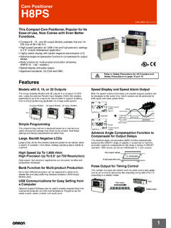
8 High-capacity loads. The fixed rivet contact is usually Silver processed so that it has a groove to (2) Terms for Configuration and Structure Silver eliminate compounds that may be generated as a result of switching. switch Configuration and Structure Rivet plated Furthermore, to prevent the oxidation or Silver alloy Energy Conservation Support /. Environment Measure Equipment sulfidization of the silver contacts while Operating Body Gold plated the switch is stored, the contacts may A part of a machine or equipment, such as be gold-plated. a cam or dog, which operates the actuator Contacts made with silver alloy are of the switch .
9 Used for switching high current, such as the current supplied to TV sets. Actuator An actuator is a part of the switch and is a gener- (7) Contact Gap ic term that includes pushbuttons and levers. The contact gap is either , , , or mm. The contact gap is a design goal. Check the contact gap of the switch to be used if a Power Supplies /. External force imposed on In Addition the actuator is relayed to the internal spring mecha- minimum contact gap is required. The standard contact gap is nism, thus moving the mm. Even for the same switch configuration, the smaller the contact moving contact to turn the switch ON or OFF. gap of a switch mechanism is, the less the movement differential (MD).
10 Is and the more sensitivity and longer durability the switch has. Such a switch cannot ensure, however, excellent switching performance, Contact Gap A distance between the fixed con- vibration resistance, or shock resistance. tact and moving contact when they A switch becomes less sensitive when the movement differential (MD). are separated from each other, increases along with the contact gap due to the wear and tear of the Others thus enabling switching operation. Mounting Hole contacts as a result of current switching operations. If a switch with a switch Case Moving Contact Terminals contact gap of mm is used for its high sensitivity, it will be necessary Also called the housing.