Transcription of Technical Guide for PLC Basic - Omron
1 Technical Guide for PLC Basic CSM_PLC Basic_TG_E_1_1. Introduction This Guide will describe the terminology needed for Basic operation of the SYSMAC PLC (Programmable Controller), for clients new to our PLCs. This Guide does not cover Technical details regarding the setting of the FA System or PLC programming after purchase. I/O Refresh With the PLC (Programmable Controller), commands from user programs designed by the client are executed one by one and processed by reading and writing information in the internal PLC memory area (At Omron , we call this the "I/O Memory"). At the same time, packages of data from sensors/switches that are directly connected to the Basic I/O unit are exchanged with data in the PLC. internal I/O Memory, at specific times. This process to totally exchange external data and internal I/O memory data is called "I/O Refresh Operation". It is important to know the timing by which the I/O Refresh will be executed when considering the operation of the FA System and User Programs designed by the client.
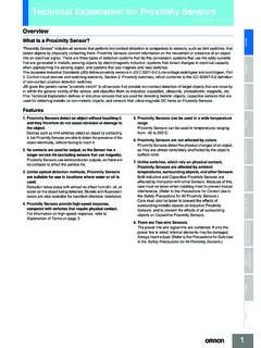
2 In the case of the SYSMAC PLC, this I/O Refresh operation is performed immediately following the execution of all other commands. (See Figure below). PLC. Inside PLC (CPU Unit). Common Processing (Self-Diagnosis). Basic I/O Unit Change (after all or built-in I/O. I/O Memory commands executed). Execute Program Package Read/Write 0 0 0 0 0 0 0 0 0 1 0 1 0 1 0 0 Exchange 0 0 0 0 0 0 0 0 0 1 1 0 1 0 1 0. PLC 1 1 0 1 1 0 0 0 1 1 0 0 1 0 1 0. Processing Cycle 0 0 1 1 1 0 1 0 1 0 1 1 1 0 1 1. 1 0 1 0 1 0 0 1 1 0 0 0 1 1 0 1. I/O Refresh Refresh with external devices Peripheral Servicing External Data (Sensor, Switch, Actuator etc.). Cycle Time In terms of the PLC processing cycle, the cycle time is the time from the execution (commencement) of the I/O Refresh operation to the execution (processing) of the following I/O Refresh. The cycle time includes time for overhead processing (self-diagnosis), execution of user programs, I/O Refresh processing and the processing of peripheral services.
3 When the cycle time is long, the cycle for updating data from outside of the PLC and the I/O response time are also longer, making it impossible to implement changes that are input at a rate faster than the cycle time. When the cycle time is short, I/O response time is also shortened, which allows high speed processing. As the cycle time changes, the command execution cycle and I/O response times also change. In the case of the SYSMAC PLC, the cycle time can be requested in the following manner: Cycle Time = Overhead Processing Time + Total Command Execution Time + I/O Refresh Time + Peripheral Service Time The calculation methods for each execution time for the SYSMAC PLC are included in the product manual. 1. Interrupt Tasks Normally, user programs are executed in order along with the processing of the I/O Refresh etc., within the PLC processing cycle (See "I/O Refresh"). Interrupt Tasks however are executed in precedence to this processing cycle.
4 In the event that certain interrupt conditions are met, the processing cycle will be suspended and the interrupt tasks will be executed first. (The SYSMAC PLC sometimes refers to the "Interrupt Tasks" as "Interrupt Programs", but here we shall use "Interrupt Tasks", the terminology used in the CS/CJ Series manuals). For example, in the case of the CS/CJ Series, Interrupt Tasks can include power Off interrupt, Scheduled Interrupts, I/O Interrupts, Periodic Interrupts based on the internal timer, and External Interrupts. Major Interrupt Tasks Details Power Break Interrupt Tasks Executed during a power break. Scheduled Interrupt Tasks Executed based on a specific schedule. I/O Interrupt Tasks Executed at the start-up of a connected Interrupt Input Unit. Executed when requests are received from the Special I/O unit, the CPU Bus Unit, and the INNER Board (only for CS. External Interrupt Tasks Series). I/O Allocation In order for user programs to utilize I/O signals from the I/O Units mounted to the PLC, it is necessary to first assign an address within the PLC I/.
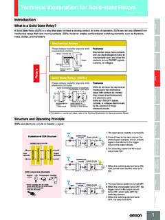
5 O Memory. The assignment of I/O Memory to the input or output from these units within the PLC is known as I/O Allocation. The CPU Unit uses this I/O. Allocation information in the operation of I/O Refresh with connected units. In the case of SYSMAC PLC, this I/O Allocation information is recorded in the PLC in the "Registered I/O Table". This "Registered I/O Table" can be created by either automatically registering online with programming tools utilizing information from the unit built-in to the PLC, or by using programming tools to design offline and then automatically registering by transmitting the I/O table to the PLC. (Some devices may not require the creation of a Registered I/O Table, and others may not support the offline design of I/O Tables.). Online Automatic Registration CX- programmer or Registered I/O Table Programming Console Type and Location of Mounted Units "Create I/O Table". Operation CPU Unit I/O Units SYSMAC CJ/CS Series Offline Automatic Registration Type and locations of Edit Registered I/O Table the Mounted Units CX- programmer "Create I/O Table".
6 Operation CPU Unit I/O Units SYSMAC CJ/CS Series 2. CPU Unit Memory Area The PLC Unit utilizes a variety of different data including user programs, I/O Memory data and comments, CPU Unit and Special I/O units Parameters, and Registered I/O Table information etc. All of this data that is used by the PLC is stored in the memory area within the CPU unit. The SYSMAC PLC has the following types of Memory Areas, which is backed up by a battery. In the case of the SYSMAC CS/CJ Series, the content of the Memory Area is backed up using flash memory, which means that even if battery power fails, any user programs and parameter area data will not be lost. User Program Area This records user programs designed by the client. I/O Memory Area This Area is accessed by command operands. It records information such as the CIO, Internal I/O Area, holding area, auxiliary area, DM Area, EM Area, Timer Completion Flags/Present Value, Completion Flag/Present Value, Task Flags, Index Register, Data Register, Condition Flags, Clock Pulse, etc.
7 The data in the I/O Memory Area locates in or is in areas in which the contents are cleared every time the power is turned back on, and areas in which prior information is retained. (In some areas you can select whether to clear or retain.). Parameter Area This contains all of the information regarding initial parameters used by the PLC. It records information such as the PLC System Parameters, Registered I/O Table, Routing Table, and PLC Setup for CPU Bus unit. 3. Technical Guide for PLC-based Process Control CSM_PLC Process_TG_E_1_1. What is the Omron PLC-based Process Control? Omron PLC-based Process Control system is based on the SYSMAC CS/CJ PLC Series. By adding PLC-based Process Control units to the Basic system configuration, PLC process control functions can be simply added on to the Basic functions already installed in the PLC. Thus, it can be used for devices that it is compatible with such process control system in which DCS was used before or devices in which several controllers were used combined.
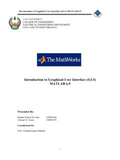
8 With the PLC Installation System, analog processing is carried out by the loop control section or the loop control unit/board (hereafter "loop controller"), and ladder processing is handled by the CPU. Communication between the two sections is made using bits of memory. Since the analog processing and ladder processing can be completely separated and the program is more simple than a ladder only program, the engineering process to construct the system is facilitated. System configuration of PLC-based process control The loop controller does not have an external analog I/O or an external contact I/O function. It is used together with such a unit that has the interface function including an analogue I/O unit, as shown in the diagram below. PLC. PT or HMI. Software Programming /Monitor PC Compensating 4 to 20 mA. 4 to 20 mA 4 to 20 mA 4 to 20 mA 4 to 20 mA Leadwire Thermo Couple Sensor Flow rate Sensor Capacitive Flow Rate Process Sensor Also, when programming, in addition to the programming software for the CPU Unit (CX- programmer , additional programming software (CX- Process) will be required to create Function block data.)
9 And in order to monitor and alter settings during operation, a HMI section will also be required, in combination with the application in use. Operation/Display Screen Creation CX-Process Tool Program Creation Section Control Block/Sequence Creation CX- programmer Batch management, brand management, remote Application Section surveillance (Web) Third Party Products etc HMI Section Data gathering, data analysis Operation/Display Meter screen, graphics screen, trends, CX-Process Monitor Plus Section Warning history, operational history, operational Guide NS Series etc. Loop Controller Loop Control Board/Unit Control Section Loop Control Section Function Block (FBD), Sequence Table, Step ladder ( or Process CPU/Loop CPU. Loop Control Section ). Sequence Control Ladder, FB (Ladder/ST Language) CS/CJ Series CPU. Section Signal I/O Section Analog I/O, Digital I/O, Pulse Input Process/Analog I/O Unit Temperature, Current/Voltage, Isolator, Pulse, Digital I/O Unit etc.
10 Signal Conversion (Signal Conditioner). Distributor Field Device Sensor, Actuator 1. Installation of PLC Control Panel CSM_PLC Installation_TG_E_1_1. Introduction In order to ensure the reliability and security of the system, prior to the design of the system it is important to make certain that the conditions in which it will be installed is well understood. Basically, the stresses on the PLC system (temperature, humidity, vibrations, shocks, corrosive gases, overcurrent, noise etc.) need to be reduced as much as possible. However, the extent to which measures need to be taken in this regard will depend upon the likelihood of problems arising, the conditions in which the system is installed, and the cost of implementing measures. By taking advanced measures to prevent problems, the reliability of the system can be improved, and in the long-term the operation rate can also be increased. For the individual specifications of each unit, please see the respective user manuals.