Transcription of Technical Information Omnigrad M TR11 - Endress
1 TI257T/02/en71073147 Technical InformationOmnigrad M tr11 Modular RTD assemblyprotection tube, threadApplication Universal range of application Measuring range: C ( F) Pressure range up to 50 bar (725 psi) Degree of protection: up to IP 68 Head transmittersAll Endress +Hauser transmitters are available with enhanced accuracy, reliability and cost effectiveness compared to directly wired sensors. Easy customizing by choosing one of the following outputs and protocols: Analog output mA HART PROFIBUS PA FOUNDATION Fieldbus Your benefits High flexibility due to modular assembly with standard terminal heads and customized immersion length Highest possible compatibility with a design according to DIN 43772 Fast response time with reduced/tapered tip form Types of protection for use in hazardous locations.
2 Intrinsic Safety (Ex ia)Non-Sparking (Ex nA)4 0TR112 Endress +HauserFunction and system designMeasuring principleThe Resistance Temperature Detector (RTD) element has an electrical resistance with a value of 100 at 0 C (32 F). It is commonly known as Pt100 and complies with IEC 60751. This resistance value increases at higher temperatures according to the characteristics of the resistor material (platinum). These kind of sensors are called Positive Temperature Coefficient elements (PTC).The coefficient is fixed with = C-1, calculated between 0 and 100 C (32 and 212 F), according to ITS90 (International Temperature Scale 1990).
3 Wire wound platinum resistance thermometers (WW) consist of hair thin highly purified platinum wire double wound inside a ceramic carrier. This is then sealed top and bottom with a ceramic protective layer. The measurements achieved by these resistance thermometers are not only highly reproducible, but also show long term resistance/temperature characteristic stability within temperature ranges up to 600 C (1112 F). This sensor type is relatively large in its dimensions and is also not very resistant to film platinum resistance thermometers (TF) consist of a precise amount of platinum which is vaporized under vacuum onto a ceramic substrate to a thickness of 1 m.
4 This is then protected by a glass layer. The advantages are: smaller dimensions than wire wound and greatly improved vibration resistance. Thin film resistances (TF) are flat, microscopic versions of the wire wound types (WW) with a measurement relevant difference:The temperature expansion behavior of the different layers of this structure leads to minimal mechanical stress. Temperature changes in thin film resistances (TF) cause the desired temperature relevant changes of the resistance as well as minimal tension stress related resistance changes.
5 Through this the resistance/temperature characteristic of most thin film platinum resistance thermometers (TF) differs considerably from the standard characteristics at higher temperatures. Thin film resistances are therefore used for temperature measurement in ranges below 500 C (932 F).Measuring systema0009536 Example of an applicationABuilt-in RTD assembly tr11 with head transmitterBRIA261 Field display The display measures an analog measurement signal and indicates this on the display. The display is connected in a 4 to 20 mA current loop and also derives its supply from the loop.
6 The voltage drop is almost negligible (< V). The dynamic internal resistance (load) makes sure that independently from the loop current, the maximum voltage drop is never exceeded. The analog signal at the input is digitalized, analyzed, and shown in the rear illuminated display. For details see Technical Information (see chapter "Documentation").CActive barrier RN221N The RN221N active barrier (24 V DC, 30 mA) has a galvanically isolated output for supplying voltage to loop powered transmitters. The power supply has a wide-range input for mains power, 20 to 250 V DC/AC,50/60 Hz to be used in any electrical circuit.
7 For details see Technical Information (see chapter "Documentation"). tr11 Endress +Hauser3 Equipment architecturea0009537 Equipment architecture of the Omnigrad M tr11 The Omnigrad M tr11 RTD assemblies are modular. The terminal head serves as a connection module for the protection armature in the process as well as for the mechanical and electrical connection of the measuring insert. The actual RTD sensor element is fitted in and mechanically protected within the insert. The insert can be exchanged and calibrated even during the process.
8 Either ceramic terminal blocks or transmitters can be fitted to the internal base washer. tr11 RTD assemblies are constructed without a range-200 .. 600 C ( F) according to IEC 60751 Performance characteristicsOperating conditionsAmbient temperature1 2 Insert ( 3 mm, in) with mounted headtransmitter, for exampleInsert ( 6 mm, in) with mounted ceramicterminal block, for example66a6bEVarious tip shapes - detailed Information see chapter tip shape :Reduced or tapered for inserts with 3 mm ( in)Straight or tapered for inserts with 6 mm ( in)Neck tube = 35 mm ( in)3 Terminal headL Immersion length4 Protection armatureIL Insertion length = L + 45 mm ( in)5 Threads as process connectionTerminal headTemperature in C ( F)Without mounted head transmitter Housing, material aluminum -40 to 100 C (-40 to 212 F) Housing, material polyamide -40 to 85 C (-40 to 185 F)With mounted head transmitter-40 to 85 C (-40 to 185 F)
9 With mounted head transmitter and display -20 to 70 C (-4 to 158 F)TR114 Endress +HauserProcess pressureThe pressure values to which the protection tube can be subjected at the various temperatures are illustrated by the figures permitted process pressure for tube diameter Tube diameter 9 x 1 mm ( in) ----------- Tube diameter 12 x mm ( in) - - - - - -Maximum flow velocityThe highest flow velocity tolerated by the protection tube diminishes with increasing immersion length exposed to the stream of the fluid. Detailed Information may be taken from the figures velocity depending on the immersion length Tube diameter 9 x 1 mm ( in) ----------- Tube diameter 12 x mm ( in) - - - - - -Shock and vibration resistance4g / 2 to 150 Hz as per IEC 60068-2-60501001502002503003501502002503 00350400P (bar)0150200250300350400L (mm)P (bar)50100150200250300350 ABL (inch)681012070021002900P (PSI)14001416681012141636004300500007002 1002900P (PSI)1400360043005000L (mm)L (inch)AMedium water at T = 50 C (122 F)
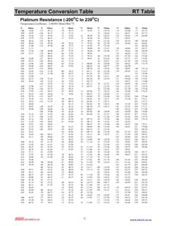
10 LImmersion lengthBMedium superheated steam at T = 400 C (752 F)PProcess pressureAMedium water at T = 50 C (122 F)LImmersion lengthBMedium superheated steam at T = 400 C (752 F)vFlow velocityTR11 Endress +Hauser5 AccuracyRTD corresponding to IEC 60751!Note! For measurement errors in F, calculate using equations above in C, then multiply the outcome by timeTests in water at m/s ( ft/s), according to IEC 60751; 10 K temperature step changes:!Note! Response time for the sensor assembly without resistanceInsulation resistance 100 M at ambient resistance between each terminal and the sheath is tested with a voltage of 100 V Tolerances ( C)Temperature rangeCharacteristicsRTD max.