Transcription of Analog linearization of resistance temperature …
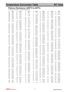
1 texas instruments Incorporated General Interest Analog linearization of resistance temperature detectors By Bruce Trump Staff Technologist resistance temperature detectors (RTDs). Figure 1. resistance of Pt100 RTD versus temperature are commonly used in industrial and scien- tific temperature measurements. The most common types are pure platinum (Pt) 400. formed into wire or evaporated in a thin film on a substrate. They rely on the funda- 350. mental temperature -dependent resistance 300. properties of this noble metal. They are very stable and useful at temperatures resistance ( ). 250. ranging from cryogenic to over 800 C. A. wide range of physical configurations, 200. resist ance ranges and accuracies is avail- Curvature due to 100 at 0 C second-order The commonly used notation Pt100 150.
2 Nonlinearity indicates a 100-W resistance at 0 C. The 100. relationship between the RTD's resistance and temperature is described by the 50. Callendar-Van Dusen equation, RRTD = R0[1 + AT + BT2 + C(T 100)T3], 0. 100 0 100 200 300 400 500 600 700 800. whose values are defined as follows: temperature ( C). R0 is a 100-W resistance at 0 C (Pt100). A = 10 3. B = 10 7. C = 0 for T > 0 C, or C = 10 12 for T < 0 C. When the RTD is excited with a current source, the The resistance of a Pt100 RTD increases with tempera- resulting RTD voltage is directly proportional to the resist . ture at approximately C. While they are far more ance, yielding the same nonlinearity. If, however, the excita.
3 Linear than thermocouples, RTDs have a significant tion current is gradually increased as the RTD temperature second-order nonlinearity of approximately per 100 C measurement range (see Figure 1). This nonlinearity is often corrected Figure 2. RTD voltage versus temperature digitally, but there are many applications for purely Analog processing and linearization of the RTD. RTD voltage is This article explains an Analog technique for gradually boosted with increasing linearization of the RTD. The same technique is excitation current also used with bridge sensors such as pressure and load cells. The principles can be applied to VOUT. RTD Voltage A. other ratiometric devices with primarily second- order nonlinearity; , any sensor or system with an output that is proportional to an excita- RTD.
4 Tion voltage or current. RTD resistance The exaggerated graph in Figure 2 shows that with second-order nonlinearity the temperature coefficient decreases with (exaggerated). increasing temperature , producing an upward bow in the middle. Above 0 C, standardized data for the Pt100 has a purely second-order or para- bolic function. Assuming calibration at two end- RTD temperature point temperatures , this produces an error that is greatest at the midpoint temperature . 21. Analog Applications Journal 4Q 2011 High-Performance Analog Products General Interest texas instruments Incorporated is increased, the nonlinearity can be greatly Figure 3. Percentage of RTD error versus temperature reduced.
5 Figure 2 shows an increasing excitation current derived from the output of the amplified RTD voltage. This current is, in effect, a controlled amount of positive feedback. It yields an interesting chicken- or-egg dichotomy: The RTD voltage at the Nonlinearity of RTD. input of the amplifier is linearized when the for 900 C span output of the amplifier is linearized and vice versa. The correct amount of positive Error ( %). Corrected output with feedback results in both. nonlinearity peaks When positive feedback is optimized, a at and scale much smaller s-shaped error remains with Zero error at nearly equal negative and positive values, midscale and reaching maximums at and full scale endpoints (see Figure 3).
6 This primarily third-order nonlinearity does not come from the RTD. but is an artifact of the linearization tech- nique. Its magnitude depends on the tem- 100 0 100 200 300 400 500 600 700 800. perature range chosen for linearization . temperature ( C). Figure 3 shows the initial nonlinearity error for a 100 C to +800 C temperature range a 900 C span. The RTD non- linearity at midscale is reduced to approxi- mately , a 33:1 improvement. The Figure 4. Typical RTD configuration with error compensation improvement is even greater for narrow temperature ranges, approaching 150:1 for a 200 C range. R2. +. The use of positive feedback might raise VREF k . R3. 5V. the concern of possible circuit instability.
7 K . The magnitude of this feedback is small R1. enough, however, to have negligible effect k A1. on the stability of commonly used circuits. OPA188. VOUT. Figure 4 shows a practical implementation 0 C to 0 V at 0 C. of an RTD. R1 provides the primary excita- 200 C + 5 V at 200 C. tion current from VREF , a stable voltage reference. R5 provides the temperature - Pt100. varying component of excitation current 100 R5. R4. from the output of A1. R2, R3, and R4 set 1 k . k . the required amplifier gain and offset to produce the desired output-voltage range. The texas instruments (TI) OPA188*. shown in this example is a new low-noise, chopper-stabilized operational amplifier that contributes negligible error to the circuit.
8 Its very low solving the nodal equation that relates the RTD voltage, and stable offset voltage makes it a possible upgrade to RTD resistance , VREF, R1, R5, and VOUT : TI's OPA277 precision industrial amplifier. The resistor values to achieve best correction can be R RTD R5 R RTD R1. calculated with iterative techniques. Many designers might R RTD + R5 R RTD + R1. optimize this type of circuit by using creative calculations VRTD = VREF + VOUT . or approximations. A closed-form solution is possible by R RTD R5 R RTD R1. + R1 + R5. R RTD + R5 R RTD + R1. *The OPA188 is expected to be available in early 2012. For general specifica- tions, please refer to the dual version, OPA2188, at OPA2188.
9 22. High-Performance Analog Products 4Q 2011 Analog Applications Journal texas instruments Incorporated General Interest Three conditions must be met to achieve Figure 5. Correlation of excitation current to RTD error zero error at the calibration endpoint tem- peratures and the midpoint temperature . Three separate variations of the preceding 16. equation are written to describe the three zero-error conditions and are solved simul- 14. taneously for the only unknown variable, 12. R5. The resistance of the RTD at the mid- point temperature is not halfway between 10 Required change in Percent (%). the endpoint resistances. This midpoint excitation current condition holds the key to the solution for 8.
10 Best linearity correction. The math yields three results for R5; only 6. one is a positive resistance . The expres sion Uncorrected 4. for R5 is very long and impractical to pre RTD error sent here. To download an Excel work- 2. sheet that provides the calculations, go to and click 0. Open to view the WinZip directory online 0 100 200 300 400 500 600 700 800. (or click Save to download the WinZip file temperature Measurement Span ( C). for offline use). Then open the file RTD_. to view the calculation worksheet. This closed-form solution is intellectually satisfying and avoids possible problems with convergence, but the results Figure 6. Amplifier with three-wire RTD connection are no better than those produced with iterative calculations.