Transcription of SLUSAG1B MARCH 2011 REVISED OCTOBER 2011 …
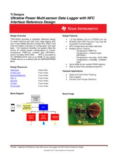
1 TPS51219. SLUSAG1B MARCH 2011 REVISED OCTOBER 2011. High Performance, Single-Synchronous Step-Down Controller with Differential Voltage Feedback 1 FEATURES DESCRIPTION.. 23 Differential Voltage Feedback The TPS51219 is a small-sized single buck controller with adaptive on-time control. It provides a choice of DC Compensation for Accurate Regulation control modes (D-CAP or D-CAP2 ) to meet a Wide Input Voltage Range: 3 V to 28 V wide range of system requirements. It is designed for Output Voltage Range: V to V with tight DC regulation requirements such as the VCCIO. Fixed Options of V and V application for Intel notebooks. The performance and flexibility of the TPS51219 makes it suitable for Wide Output Load Range: 0 A to 20 A+ low output voltage, high current, PC system power Adaptive On-Time Modulation with Selectable rails and similar point-of-load (POL) power supplies. Control Architecture and Frequency Differential voltage feedback and the voltage D-CAP Mode at 300 kHz/400 kHz for Fast compensation function combine to provide high Transient Response precision power to load devices.
2 D-CAP2 Mode at 500 kHz/670 kHz for A small package, fixed voltage options and minimal Ceramic Output Capacitor external component count saves cost and space, while a dedicated EN pin and pre-set frequency 4700 ppm/ C, Low-Side RDS(on) Current Sensing selections minimize design effort. The skip-mode at RSENSE Accurate Current Sense Option light load condition, strong gate drivers, and low-side Internal, 1-ms Voltage Servo Softstart FET RDS(on) current sensing provides high efficiency operation over a broad load range. The external Built-In Output Discharge resistor current sense option enables accurate Power Good Output current sensing. The conversion input voltage (the Integrated Boost Switch high-side FET drain voltage) ranges from 3 V to 28 V. Built-In OVP/UVP/OCP and output voltage ranges from V to V. The device requires an external 5-V supply. Thermal Shutdown (Non-latched). The TPS51219 is available in a 16-pin, QFN package 3 mm 3 mm, 16-Pin, QFN (RTE) Package and is specified for ambient temperature from -40 C.
3 To 85 C. APPLICATIONS. Notebook Computers I/O Supplies VIN. V5IN. PGOOD. EN. 16 15 14 13. MODE. PwrPd BST. PGOOD. EN. SW 12. 1 VREF. DH 11. 2 REFIN. TPS51219 RTE VOUT. GSNS 3 GSNS V5 9. COMP. PGND. TRIP. GND. VSNS 4 VSNS DL 10. 5 6 7 8. UDG-11006. 1. Please be aware that an important notice concerning availability, standard warranty, and use in critical applications of Texas Instruments semiconductor products and disclaimers thereto appears at the end of this data sheet. 2 D-CAP, D-CAP2 are trademarks of Texas Instruments. 3 Intel is a registered trademark of Intel. PRODUCTION DATA information is current as of publication date. Copyright 2011, Texas Instruments Incorporated Products conform to specifications per the terms of the Texas Instruments standard warranty. Production processing does not necessarily include testing of all parameters. TPS51219. SLUSAG1B MARCH 2011 REVISED OCTOBER 2011 These devices have limited built-in ESD protection.
4 The leads should be shorted together or the device placed in conductive foam during storage or handling to prevent electrostatic damage to the MOS gates. ORDERING INFORMATION (1). ORDERABLE DEVICE OUTPUT MINIMUM. TA PACKAGE PINS. NUMBER SUPPLY QUANTITY. TPS51219 RTER Tape and reel 3000. 40 C to 85 C Plastic Quad Flat Pack (QFN) 16. TPS51219 RTET Mini-reel 250. (1) For the most current package and ordering information see the Package Option Addendum at the end of this document, or see the TI. web site at ABSOLUTE MAXIMUM RATINGS (1). over operating free-air temperature range (unless otherwise noted). VALUE UNIT. MIN MAX. BST 36. BST (3) 6. SW 5 30. Input voltage range (2) EN, MODE, TRIP, V5 V. COMP, REFIN, VSNS GSNS PGND DH 5 36. (3). DH 6. Output voltage range (2) DL 6 V. PGOOD 6. VREF Junction temperature range, TJ 125 C. Storage temperature range, TSTG 55 150 C. (1) Stresses beyond those listed under absolute maximum ratings may cause permanent damage to the device.
5 These are stress ratings only and functional operation of the device at these or any other conditions beyond those indicated under recommended operating conditions is not implied. Exposure to absolute-maximum-rated conditions for extended periods may affect device reliability. (2) All voltage values are with respect to the network ground terminal unless otherwise noted. (3) Voltage values are with respect to the SW terminal. 2 Submit Documentation Feedback Copyright 2011, Texas Instruments Incorporated TPS51219. SLUSAG1B MARCH 2011 REVISED OCTOBER 2011. RECOMMENDED OPERATING CONDITIONS. MIN TYP MAX UNIT. Supply voltage V5 V. BST BST (1) SW -3 28. SW (2) 28. Input voltage range V. EN, TRIP, MODE REFIN, VSNS, COMP GSNS PGND DH 3 DH (1) DH (2) Output voltage range V. DL PGOOD VREF TA Operating free-air temperature 40 85 C. (1) Voltage values are with respect to the SW terminal. (2) This voltage should be applied for less than 30% of the repetitive period.
6 THERMAL INFORMATION. TPS51219. THERMAL METRIC (1) RTE UNITS. 16 PINS. JA Junction-to-ambient thermal resistance (2) JCtop Junction-to-case (top) thermal resistance (3) JB Junction-to-board thermal resistance (4) (5). C/W. JT Junction-to-top characterization parameter JB Junction-to-board characterization parameter (6) JCbot Junction-to-case (bottom) thermal resistance (7) (1) For more information about traditional and new thermal metrics, see the IC Package Thermal Metrics application report, SPRA953. (2) The junction-to-ambient thermal resistance under natural convection is obtained in a simulation on a JEDEC-standard, high-K board, as specified in JESD51-7, in an environment described in JESD51-2a. (3) The junction-to-case (top) thermal resistance is obtained by simulating a cold plate test on the package top. No specific JEDEC-standard test exists, but a close description can be found in the ANSI SEMI standard G30-88. (4) The junction-to-board thermal resistance is obtained by simulating in an environment with a ring cold plate fixture to control the PCB.
7 Temperature, as described in JESD51-8. (5) The junction-to-top characterization parameter, JT, estimates the junction temperature of a device in a real system and is extracted from the simulation data for obtaining JA, using a procedure described in JESD51-2a (sections 6 and 7). (6) The junction-to-board characterization parameter, JB, estimates the junction temperature of a device in a real system and is extracted from the simulation data for obtaining JA , using a procedure described in JESD51-2a (sections 6 and 7). (7) The junction-to-case (bottom) thermal resistance is obtained by simulating a cold plate test on the exposed (power) pad. No specific JEDEC standard test exists, but a close description can be found in the ANSI SEMI standard G30-88. Copyright 2011, Texas Instruments Incorporated Submit Documentation Feedback 3. TPS51219. SLUSAG1B MARCH 2011 REVISED OCTOBER 2011 ELECTRICAL CHARACTERISTICS. over operating free-air temperature range, VV5 = 5 V, VMODE= 0 V, VEN= 5 V (unless otherwise noted).
8 PARAMETER TEST CONDITION MIN TYP MAX UNIT. SUPPLY CURRENT. IV5 V5 supply current TA = 25 C, No load, VEN = 5 V 560 A. IV5 SDN V5 shutdown current TA = 25 C, No load, VEN = 0 V A. VREF OUTPUT. VVREF Output voltage IVREF = 0 A wrt GSNS V. 0 A IVREF < 30 A, TA = 0 C to 85 C VVREF(tol) Output voltage tolerance 0 A IVREF < 300 A, TA = 40 C to 85 C IVREF(ocl) Current limit VVREF-GSNS = V mA. OUTPUT VOLTAGE. VREFIN = 0 V V. VVSNS VSNS sense voltage VREFIN = V V. V VREFIN 2 V VREFIN V. VREFIN = 0 V, 0 C TA 85 C 9 9. VREFIN = 0 V, -40 C TA 85 C -14 14. VVSNS(tol) VSNS regulation voltage tolerance VREFIN = V, 0 C TA 85 C 9 9 mV. VREFIN = V, -40 C TA 85 C -14 14. VREFIN = V and VREFIN = V -5 5. VREFIN1 REFIN voltage for output V. VREFIN1P05 REFIN voltage for output V. VOFF_LPCMP Loop comparator offset voltage VREFIN = 1 V, VSNS shorted to COMP -5 5 mV. VREFIN = 0 V, VVSNS = V V. VCOMPCLP COMP clamp voltage VREFIN = 0 V, VVSNS = V V. gM Error amplifier transconductance VREFIN = 0 V 130 S.
9 IVSNS VSNS input current VVSNS = V -1 1 A. IREFIN REFIN input current VREFIN = 0 V 1 1 A. IVSNS(dis) VSNS discharge current VEN = 0 V, VVSNS = V 5 12 mA. SWITCH MODE POWER SUPPLY (SMPS) FREQUENCY. VIN = 12 V, VVSNS = V, VMODE = V 400. VIN = 12 V, VVSNS = V, VMODE = V 300. fSW Switching frequency kHz VIN = 12 V, VVSNS = V, VMODE = V 670. VIN = 12 V, VVSNS = V, VMODE = V 500. tON(min) Minimum on time DH rising to falling (1) 60. ns tOFF(min) Minimum off time DH falling to rising 320. MOSFET DRIVERS. Source, IDH = 50 mA RDH DH resistance Sink, IDH = 50 mA . Source, IDL = 50 mA RDL DL resistance Sink, IDL = 50 mA DH-off to DL-on 10. tDEAD Dead time ns DL-off to DH-on 20. INTERNAL BOOT STRAP SWITCH. VFBST Forward voltage VV5-BST, TA = 25 C, IF = 10 mA V. IBSTLK BST leakage current TA = 25 C, VBST = 33 V, VSW = 28 V A. (1) Ensured by design. Not production tested. 4 Submit Documentation Feedback Copyright 2011, Texas Instruments Incorporated TPS51219.
10 SLUSAG1B MARCH 2011 REVISED OCTOBER 2011. ELECTRICAL CHARACTERISTICS (continued). over operating free-air temperature range, VV5 = 5 V, VMODE= 0 V, VEN= 5 V (unless otherwise noted). PARAMETER TEST CONDITION MIN TYP MAX UNIT. LOGIC THRESHOLD. IMODE MODE source current A. MODE 0-1 113 143 173. MODE 1-2 253 283 313. MODE 2-3 433 458 483. VTHMODE MODE threshold voltage MODE 3-4 644 667 690 mV. MODE 4-5 914 949 984. MODE 5-6 1329 1369 1409. MODE 6-7 1950 2000 2050. VLL EN low-level voltage VLH EN high-level voltage V. VLHYST EN hysteresis voltage ILLK EN input leakage current 1 0 1 A. SOFT START. tSS Soft-start time Internal soft-start time ms POWERGOOD COMPARATOR. PGOOD in from higher 106% 108% 110%. PGOOD in from lower 90% 92% 94%. VTHPG PGOOD threshold PGOOD out to higher 114% 116% 118%. PGOOD out to lower 82% 84% 86%. IPG PGOOD sink current VPGOOD = V 3 6 mA. Delay for PGOOD in ms tPGDLY PGOOD delay time Delay for PGOOD out, with 100 mV over drive s tPGCMPSS PGOOD start-up delay PGOOD comparator wake-up delay ms IPG(leak) PGOOD leakage current -1 0 1 A.