Transcription of Technical Note: Glulam Beam Camber
1 Technical NOTEG lulam beam CamberNumber S550H February 2015 One of the most important design qualities of wood framing is its resilience under load. Wood s unique stiffness makes wood floors comfortable to walk, work and stand on. These qualities also contribute greatly to wood s excel-lent damping characteristics, thus giving wood-framed structures the ability to absorb impact size and span capabilities of sawn lumber beams are generally limited by the physical characteristics of the tim-ber supply. Consequently, stiffness, or deflection under load, at the relatively short spans commonly used with sawn lumber beams is seldom a governing factor in the design of these wood structural elements. With the availability of glued laminated timber ( Glulam ), it is possible for architects and engineers to design wood members in large sizes and long professionals recognize that for long spans, design is often controlled by deflection limits rather than by beam strength.
2 One way to reduce the adverse aesthetic effect and structural significance of beam deflection is through the use of Camber . Camber is an initial curvature built into a fabricated member, such as a Glulam , which is opposite in direction to the calculated deflection, which will occur under gravity loads. The use of Camber in Glulam beams also gives the designer the ability to negate the possible adverse effects of long-term deflection or creep, which may occur with wood this Technical Note provides a discussion of Camber , it is important to recognize that building codes do not require this technique for deflection control. It is only one of several options available to the designer. Other design techniques for providing deflection control include specifying beams of greater stiffness than otherwise would be required, increasing slope for roof drainage to minimize possible effects of ponding, or limiting spans such that deflection is not a controlling design some situations, especially in construction applications where the framing elements are rarely subjected to speci-fied design live loads and the deflection due to dead loads is minimal, Camber may not be necessary.
3 In such applica-tions, Camber designed into a beam may never relax. In floor construction this can cause a permanent, unwanted crown and, in multi-story applications, it may increase the difficulty of framing successive floors during construction. As a general rule, if noncambered sawn lumber beams have traditionally performed well in a given application, then cambering is probably not required when a Glulam having equivalent or greater stiffness is substituted. Residential garage door headers and floor beams are good examples of uses where Camber may not be No. S550H 2015 APA The Engineered Wood Association 2 Glulam beam CamberCONTROLLING DEFLECTIONB uilding code limits on beam deflection were first imposed in the early 1900s to prevent the cracking of brittle plaster ceilings. The deflections determined for this serviceability requirement remain as the basis for the allowable deflec-tions listed in building codes code requirements aside, the appearance of a sagging floor or roof beam does not instill structural con-fidence in the eye of the beholder.
4 While a sagging beam may have sufficient strength to support its design loads, it may be perceived as being under designed and may adversely affect the acceptance of the overall building design. Glulam is generally the only engineered wood beam that can be addition to the aesthetic reasons mentioned above, there is a structural reason for limiting deflection in large flat roofs. This is to prevent ponding which may occur when water collects in a depression in a flat roof. As water builds up in a depression, the load on the supporting members increases. This causes additional deflection, which permits more water to accumulate. Once initiated, this cycle can continue until a roof failure occurs. Ponding is more prevalent in areas where roofs are designed for low live-to-dead-load ratios. Roofs designed for snow loads are typically stiffer and have a greater ability to resist ponding than similar roofs designed only for relatively light construction general guideline for determining if provisions to prevent ponding are necessary is to compute the deflection of the member in question under a uniform load of 5 lbf per sq.
5 Ft. If the resulting deflection is equal to or greater than 1/2 inch, this is an indication that ponding is a potential problem and beam Camber combined with other positive means to ensure drainage should be used. This simplified procedure should not be substituted for a detailed engi-neering analysis to control ponding of low slope or flat RECOMMENDATIONSC alculated beam deflection is used to assess compliance with specifications, the building code, and to specify beam Camber . This calculated deflection is measured from a plane connecting the beam supports. When Camber is built into the beam , the built-in deflection is above this code-specified deflection limit may be measured from the plane connecting the supports to a point below that plane. When Camber is not required to prevent ponding, a cambered beam , just as one without Camber , may be per-mitted to deflect below the plane connecting the supports by the amount permitted in the code.
6 This is acceptable provided that the beam is not over-stressed, and adjacent construction (such as plaster walls or ceilings), machinery, and objects connected to or resting on the beam are not adversely affected by this most roof beam applications, the Glulam industry recommends the use of 1-1/2 times the calculated dead load deflection to arrive at Camber specifications. This amount of Camber is generally sufficient to allow the beam to deflect back to near level after many years under sustained dead load. For floor beams, the recommended Camber is times the calculated dead load addition to cambering for deflection induced by dead load, roof beams in simple-span applications may also be cambered to provide the industry recommended slope of 1/4 inch per foot to insure proper drainage. When this is done, the required Camber for slope is calculated and added to the dead-load Camber described above. This becomes the total Camber , which can be built into the beam during No.
7 S550H 2015 APA The Engineered Wood Association 3 Glulam beam CamberCAMBER TOLERANCESB ecause of the variability of mechanical and physical properties in all wood products and manufacturing associated tolerances, a cambered Glulam beam will not always be manufactured with exactly the Camber specified. In addition, moisture changes can also affect the Camber of any specific beam . For these reasons, a certain degree of variability associated with any target Camber is allowed and should be expected. Section of ANSI Structural Glued Laminated Timber gives the tolerances for Camber or straightness of a Glulam as: Up to 20 feet, the tolerance is plus or minus 1/4 inch. Over 20 feet, increase tolerance by 1/8 inch per additional 20 feet or fraction thereof, but not to exceed 3/4 inch. This variability in Camber is generally so small with respect to beam length that it is undetectable to the human eye and has little or no effect on beam Camber for beams is often specified as inches of Camber .
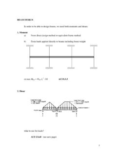
8 It may also be specified as a radius of curvature. Thus specified, the offsets at various points along a beam of any length can be represented by a single number. The circular arc formed by this method closely approximates the actual deflected curvature of the beam under load. The beam is thus fabricated with a built-in mirror image of the expected deflected 1 is a precalculated deflection/radius-of-curvature table used by fabricators. This table can be used to specify a Camber radius based on a given span and calculated beam CamberAs an alternative to using Table 1 to specify Camber , the following formula may be used to calculate the approximate radius of curvature, given the beam span and Camber Where:R = approximate radius of curvature (ft)L = span (ft) = desired Camber (in.)See Figure 1 for a graphic representation of beam Camber example of the use of radius of curvature to specify beam Camber is given as follows:Calculate the required Camber for a Glulam roof beam for the following design conditions: Glulam beam size = 6-3/4 in.
9 X 27 = x 106 psiI = 11,072 = 48 ftDead load = 120 plfBeam weight = 44 plfDead load deflection=5wL41,728384 EIw = dead load + beam weight (lb/ft)L = beam span (ft)E = Modulus of Elasticity (psi)L = Span (ft)Cambered beam = Camber (in.)R = Radius of Curvature (ft)FIGURE 1 beam Camber PARAMETERSForm No. S550H 2015 APA The Engineered Wood Association 4 Glulam beam CamberI = Moment of Inertia ( )Dead load deflection= 5(120 + 44)(484)(1,728) = in384( x 106)(11,072)Recommended Camber = x = of curvature (R) required:From Table 1, R2000 = in. for 48 ft span- or -by calculation:R=3(48)2=2,082 ft2( )Note that a Camber radius of 2,000 feet would provide a Camber of inches and should be considered for this BEAMSThe cambering of cantilevered beams is a subject that is often misunderstood. While it is theoretically possible to specify Camber for each span section of single and double cantilevered beams, it is, in most cases, not practical.
10 If the Camber does not relax, a beam with an S shaped Camber for a cantilever (or W shaped Camber in the case of a double cantilever) can severely impact roof drainage and can even cause ponding over the outside supports. Ponding over the supports can lead to bearing or support failures and subsequent roof leaks. For most typical cantilever-length to main-span-length conditions, the preferred method is to Camber only the span length between the supports, leaving the cantilevered portion uncambered. This will generally ensure good drainage of the roof system. If unusually long cantilever lengths are used, a further analysis of member deflection and Camber is war-ranted. Based on this analysis, the designer may choose to specify individual Camber values for both the interior beam span and the cantilever beam CAMBERW hile the ability to pre- Camber Glulam beams is a distinct advantage for many longer span applications, it can be a disadvantage in applications where too much Camber can cause jobsite framing problems.