Transcription of Technical Notes REVISED on Brick Construction Reissued* …
1 INTRODUCTIONA lintel is a structural member placed over an openingin a wall. In the case of a Brick masonry wall, lintels mayconsist of reinforced Brick masonry , Brick masonry arches,precast concrete or structural steel shapes. Regardlessof the material chosen for the lintel, its prime function is tosupport the loads above the opening, and it must bedesigned eliminate the possibility of structur-al cracks in the wall above these openings, the structuraldesign of the lintels should not involve the use of "rule-of-thumb" methods, or the arbitrary selection of structuralsections without careful analysis of the loads to be carriedand calculation of the stresses developed. Many of thecracks which appear over openings in masonry walls aredue to excessive deflection of the lintels resulting fromimproper or inadequate Technical Notespresents the considerations tobe addressed if structural steel lintels are to be used.
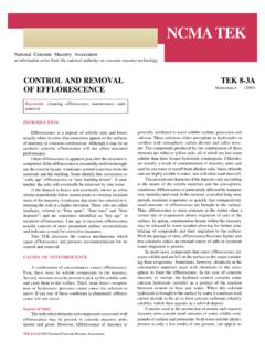
2 Italso provides a procedure for the structural design ofthese lintels. For information concerning reinforced brickmasonry lintels, see Technical Notes 17H and for brickmasonry arches, seeTechnical Notes31, 31 Aand structural steel lintels are used, there are sev-eral considerations which must be addressed in order tohave a successful design. These include loading, type oflintel, structural design, material selection and mainte-nance, moisture control around the opening, provisions toavoid movement problems and installation of the lintel inthe are several different types of structural steel lin-tels used in vary from single angle lintelsin cavity or veneer walls, to steel beams with plates insolid walls, to shelf angles in Brick veneer panel building codes permit steel angle lintels to be usedfor openings up to 8 ft 0 in.
3 ( m). Openings larger thanthis are usually required to have fire protected Angle angle lintels are used inbrick veneer and cavity wall constructions where the lintelis laid in the wall and spans the opening. This type of lin-tel has no lateral support. Figure 1a shows this Lintels. In solid masonry walls, singleloose angle lintels are usually not capable of doing thejob. Therefore, combination lintels are required. Thesecombination lintels can take many forms, from a clusteringof steel angles, such as shown in Figs. 1b and 1c, to acombination of steel beam and plates, as shown in and Lintels- In solid masonry walls, it is usually sat-isfactory to use multiple steel angles as a lintel. Theseangles are usually placed back to back, as shown in and Beam/Plate Lintels- In solid walls with large super-imposed loads, or in walls where the openings are greaterthan 8 ft 0 in.
4 ( m), it may be necessary to use lintels com-posed of steel beams with attached or suspended plates, asshown in Figs. 1d and 1e. This permits the beam to be fullyencased in masonry , and panel walls systems, the exteriorwythe of brickwork may be supported by shelf anglesrigidly attached to the structural frame. These shelfangles, in some cases, also act as lintels over openings inthe condition is shown in *May 198731 BREVISEDT echnical Noteson Brick ConstructionBrick Industry Association11490 Commerce Park Drive, Reston, Virginia 20191 STRUCTURALSTEELLINTELSA bstract: The design of structural steel lintels for use with Brick masonry is too critical an element to be left to rule-of-thumb" designs. Too little concern for loads, stresses and serviceability can lead to is provided so that structural steel lintels for use in Brick masonry walls may be Words:beams(supports); Brick ;buildings;deflection; design; lintels; loads(forces); masonry ; struc-tural steel; walls.
5 *Originally published in Nov/Dec 1981, this Technical Noteshas been reviewed and proper design of the structural steel lintel is veryimportant, regardless of the type used. The design mustmeet the structural requirements and the serviceabilityrequirements in order to perform successfully. Designloads, stresses and deflections will be covered in a latersection of this Technical proper specification of materials for steel lintels isimportant for both structural and serviceability require-ments. If materials are not properly selected and main-tained, problems can steel for lintels, as a minimum, shouldcomply with ASTM A36. Steel angle lintels should be atleast 1/4 in. (6 mm) thick with a horizontal leg of at least 31/2 in. (90 mm) for use with nominal 4 in. (100 mm) thickbrick, and 3 in.
6 (75 mm) for use with nominal 3 in. (75mm) thick harsh climates and exposures,consideration should be given to the use of galvanizedsteel lintels. If this is not done, then the steel lintels willrequire periodic maintenance to avoid ControlProper consideration must always be given to mois-ture control wherever there are openings in masonrywalls. There must always be a mechanism to channel theflow of water, present in the wall, to the and where galvanizedor stainless steel angles are used for lintels in cavity andveneer walls, continuous flashing should be installed overthe angle. It should be placed between the steel and theexterior masonry facing material to collect and divertmoisture to the outside through weepholes. Regardlessof whether flashing is used, weepholes should be provid-ed in the facing at the level of the lintel to permit theescape of any accumulated moisture.
7 See TechnicalNotes7 Afor further information on flashing and ProvisionsBecause of the diversity of movement characteristicsof different materials, it is necessary to provide for differ-ential movement of the materials. This is especially trueat locations where a number of different materials Notes18 Series provides additionalinformation on differential joints in Brick masonryare very important in preventing unnecessary and unwant-ed cracking. There are two types of expansion jointswhich will need to be carefully detailed when lintels areinvolved: vertical and Vertical expansion joints are provided to per-mit the horizontal movement of the Brick masonry . Wherethese expansion joints are interrupted by lintels, theexpansion joint should go around the end of the lintel andthen continue down the 1 Types of Structural Steel Lintels2 Horizontal - In multi-story walls where the lintels are acontinuation of shelf angles supporting masonry panels,horizontal expansion joints to accommodate verticalmovement must be provided.
8 Often a simple soft jointbelow the shelf angle is all that is needed. See TechnicalNotes18A, 21 Rev, and 28B Rev for typical installation of steel lintels in masonry walls is aconventional Construction operation, familiar to mostmembers of the building team. The walls are built to theheight of the opening, the lintel is placed over the open-ing, and the masonry work is continued. One item of spe-cial Construction that must be noted is temporary the steel lintel is beingdesigned assuming in-plane arching of the masonryabove, then the lintel must be shored until the masonryhas attained sufficient strength to carry its own shoring period should not be less than 24 time period should be increased to three dayswhen there are imposed loads to be supported. If themasonry is being built in cold weather Construction condi-tions, the length of cure should be increased.
9 If the lintelis designed for the full uniform load of the masonry andother superimposed loads ignoring any inherent archingaction, then no shoring is structural design of steel lintels is relatively sim-ple. The computations are the same as for steel beamsin a building frame, but because of the low elasticity of themasonry, and the magnitude and eccentricity of the load-ing, the design should not be taken must consider the loads, stresses, and serviceabil-ity of the system. If these are not properly taken intoaccount, problems of cracking and spellingcould determination of imposed loads is an importantfactor. Fig. 2 shows an example of a lintel design situa-tion. On the left is an elevation showing an opening in awall with planks and a beam bearing on the wall. On theright is a graphic illustration of the distribution of thesuperimposed Loads.
10 The triangular wall area (ABC) inFig. 2b above the opening has sides at 45-deg angles tothe base. Arching action of a masonry wall will carry thedead weight of the wall and the superimposed loads out-side this triangle, provided that the wall above Point B(the top of the triangle) is sufficient to provide resistanceto arching thrusts. For most lintels of ordinary wall thick-ness, loads and spans, a depth of 8 to 16 in. (200 mm to400 mm) above the apex is sufficient. If stack bondedmasonry is used, horizontal joint reinforcement must beprovided to ensure the arching arching action occurs, the dead weight ofthe masonry wall, carried by the lintel, may be safelyassumed as the weight of masonry enclosed within the tri-angular area (ABC). To the dead load of the wall must beadded the uniform live and dead loads of the floor bearingon the wall above the opening and below the apex of the45-deg triangle.